
Instructions / Assembly

3. Ceiling Fan Assembly (Continued)
10
U.L. Model No.: 52-ANT
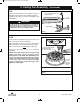
3.13
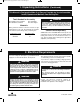
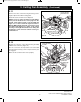
Position the switch housing assembly on the switch
h
ousing plate and align the holes in the switch housing
assembly with the holes in the plate.
S
ecure the switch housing assembly by reinstalling
the three mounting screws (previously removed)
(Figure 12).
NOTE: Do not pinch wires between the switch
housing assembly and the switch housing plate.
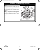
You have now completed the assembly of your new
ceiling fan. You can now proceed with hanging and
wiring your fan.
SWITCH
HOUSING
ASSEMBLY
MOUNTING
SCREWS (3)
Figure 12
BP7312-4 CF700.qxp_ BP7312 2/27/15 5:14 PM Page 10