
Instructions / Assembly

6
U.L. Model No.: 52-ANT
D
OWNROD
CLEVIS
PIN
HAIRPIN
CLIP
MOTOR
COUPLING
HAIRPIN
C
LIP
CLEVIS
P
IN
LOOSEN
SETSCREWS (2)
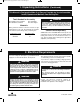
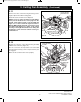
Figure 3
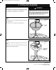
3. Ceiling Fan Assembly (Continued)
3.4
Loosen the two setscrews in the motor coupling.
P
lace the hanger ball/4.5” downrod assembly into the
motor coupling, aligning the clevis pin holes in the
downrod with the holes in the motor coupling (Figure 3).
The clevis pin must go through the holes in the motor
coupling and the holes in the downrod.
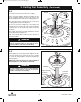
Be sure to push the straight leg of the hairpin clip
through the hole near the end of the clevis pin until the
curved portion of the hairpin clip snaps around the
clevis pin.
The hairpin clip must be properly installed to prevent
the clevis pin from working loose.
Pull on the hanger ball to make sure the clevis pin is
properly installed.
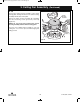
RETIGHTEN
SETSCREW
MOTOR COUPLING
RETIGHTEN
SETSCREW
DOWNROD
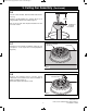
3.5
While pulling up on the hanger ball, retighten the two
setscrews (previously loosened) in the motor coupling
to secure the hanger ball/4.5” downrod assembly into
place (Figure 4).
NOTE: The setscrews must be properly installed as
described above, or fan wobble could result.
Figure 4
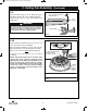
It is critical that the setscrews are securely tightened.
Failure to verify that the setscrews are properly
installed could result in the fan falling.
WARNING
!
It is critical that the clevis pin in the motor coupling is
properly installed. Failure to verify that the pin is
properly installed could result in the fan falling.
WARNING
!
BP7312-4 CF700.qxp_ BP7312 2/27/15 5:13 PM Page 6