
Instructions / Assembly

8
U.L. Model No.: 52-ANT
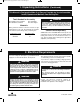
3. Ceiling Fan Assembly (Continued)
M6 x 12mm FLANGE SCREWS
WITH LOCKWASHERS
(2 per blade assembly)
MOTOR
HUB
SWITCH
HOUSING
PLATE
Figure 9
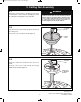
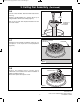
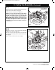
3.10
Rotate the motor hub until the flange screw hole is next
to the cutout in the switch housing plate.
Attach one blade assembly to the motor hub using two
M6 x 12mm flange screws with lockwashers in flange.
Make sure the screws are NOT tightened. (Figure 9).
Repeat this procedure for the other four blade
assemblies.
NOTE: The blade flanges have an interlocking
feature that must be fully engaged before
tightening the screws. Make sure all the flanges are
properly engaged and then tighten the flange
screws. If one of the flanges does not seat properly
on the motor hub, loosen the adjacent flange
screws, re-engage and reseat the flanges, then
tighten the screws again.
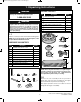
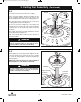
3.9
Mount the blade flange to the fan blade using three
M5 x 6mm washer head screws (supplied) (Figure 8).
Repeat this procedure for other four fan blades and
blade flanges.
FAN
BLADE
BLADE FLANGE
M5 x 6mm WASHER HEAD
BLADE SCREW (3)
Figure 8
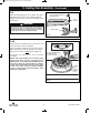
To reduce the risk of personal injury, do not bend the
blade flange when installing the blade flanges,
b
alancing the blades or cleaning the fan. Do not insert
foreign objects in between rotating fan blades
WARNING
!
BP7312-4 CF700.qxp_ BP7312 2/27/15 5:13 PM Page 8