
Instructions / Assembly


7
emersonfans.com
Please contact 1-800-654-3545 for further assistance
U.L. Model No.: 52-ANT
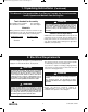
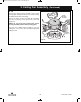
STYROFOAM
PARTIALLY ASSEMBLED
CEILING FAN
Figure 6
3.7
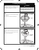
Carefully turn the partially assembled ceiling fan over
and place it on the styrofoam for final preparation
(Figure 6).
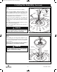
3.8
Remove the shipping spacers and the spacer
attachment screws from the motor before installation of
blade assemblies (Figure 7).
Discard the spacers and spacer screws.
SPACER ATTACHMENT SCREW
SHIPPING SPACER
Figure 7
3. Ceiling Fan Assembly (Continued)
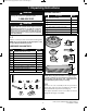
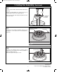
HANGER BALL/
DOWNROD
ASSEMBLY
6 to 9
INCHES
3.6
The fan comes with blue, black and white leads that are
42” long.
Measure up approximately 6 to 9-inches above top of
hanger ball/4.5” downrod assembly (Figure 5).
Cut off excess leads and strip back insulation 1/2-inch
from end of leads.
Figure 5
BP7312-4 CF700.qxp_ BP7312 2/27/15 5:13 PM Page 7