CONTEMPORARY READ AND SAVE THESE INSTRUCTIONS LURAY ECO™ 60” Damp Location Ceiling Fan Owner's Manual Model Numbers CF860BQ00 - Barbeque Black CF860PT00 - Platinum CF860WW00 - Appliance White Net Weight: 20.02 Lbs. Questions, problems, missing parts: Before returning to the store call Emerson Electric Customer Service - 8 a.m. - 6 p.m., Eastern, Monday-Friday 1-800-654-3545 Part No. F40BP75150000 Revision: 160503 www.emersonfans.com • Español - página 37 • Français - page 73 Form No.
Table of Contents Section Page Safety Instructions . . . . . . . . . . . . . . . . . . . . . . . . . . . . . . . . . . .2 1. Unpacking Instructions . . . . . . . . . . . . . . . . . . . . . . . . . . . .3-4 2. Electrical Requirements . . . . . . . . . . . . . . . . . . . . . . . . . . . . .4 3. Ceiling Fan Assembly . . . . . . . . . . . . . . . . . . . . . . . . . . . .5-10 4. How to Hang Your Ceiling Fan . . . . . . . . . . . . . . . . . . . .10-11 5. Light Kit Assembly . . . . . . . . . . . . . . . . . .
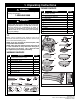
1. Unpacking Instructions WARNING ! PACKAGE CONTENTS Do not install or use fan if any part is damaged or missing. Call Toll-Free: Part A B C D E F G H I J K 1-800-654-3545 WARNING ! This product is designed to use only those parts supplied with this product and/or any accessories designated specifically for use with this product by Emerson Electric Co. Substitution of parts or accessories not designated for use with this product by Emerson Electric Co.
1. Unpacking Instructions (Continued) This Manual Is Designed to Make it as Easy as Possible for You to Assemble, Install, Operate and Maintain Your Ceiling Fan THIS FAN IS SUITABLE FOR DAMP LOCATIONS SUCH AS COVERED PORCHES, COVERED PATIOS, AND COVERED DECKS...ANYWHERE THERE IS A ROOF OVERHEAD. USE ONLY WITH LIGHT KITS MARKED SUITABLE FOR USE IN DAMP LOCATIONS.
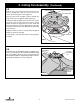
3. Ceiling Fan Assembly 3.1 FAN MOTOR ASSEMBLY Flip the upper foam pad over and place on a stable working surface. Remove the fan motor assembly from the protective plastic bag. Place fan motor assembly on top of the foam pad with the upper motor cover supporting the weight of the motor (Figure 1). This will permit access for the blades to be installed. UPPER MOTOR COVER Figure 1 3.2 Note: The blades will have screws installed from the top and bottom into the motor assembly.
3.3 3. Ceiling Fan Assembly (Continued) ROTATE CLOCKWISE Remove one of the three pan head screws from the motor assembly hub, retain the screw for future use. Loosen the remaining two screws (Figure 3). LIGHT KIT ADAPTER PAN HEAD SCREW Place the 2-pin motor assembly connector through the large center hole of the light kit adapter (Figure 3). Position the light kit adapter key hole slots onto the two loosened screw heads. Rotate the switch housing adapter clockwise to engage the two screws.
3.5 3. Ceiling Fan Assembly NOTE: Installation of the blade will be complete after this step: (Continued) BLADE SCREWS (2 per blade assembly) Align the two blade tab holes of one blade with the threaded holes of the motor and install a washer head screw into each hole (Figure 5). BLADE ASSEMBLY (3) Loosely fasten each screw into the motor ear. It will be necessary push on the blade with your hand to align the holes. Have patience during this step.
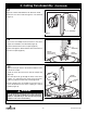
3. Ceiling Fan Assembly 3.7 (Continued) TWO 80" MOTOR LEADS (UNTWISTED) Separate, untwist and unkink the two 80” motor leads. Route the two motor leads through the 4.5” downrod (Figure 7). 4.5" DOWNROD Figure 7 3.8 Loosen the two Phillips head setscrews in the motor coupler for installation of the downrod (Figure 8). Seat the downrod in the motor coupler (Figure 8). 4.5" DOWNROD Rotate and align the downrod holes with all the holes in the motor coupler (Figure 8).
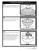
3.10 3. Ceiling Fan Assembly (Continued) 4.5" DOWNROD Make sure the grommet is properly installed in the motor coupler cover, then slide the motor coupler cover on the downrod until it rests on the motor housing (Figure 10). COUPLER COVER GROMMET COUPLER COVER Figure 10 3.11 Place the ceiling cover over the downrod (Figure 11). Be sure that the ceiling cover and the motor coupler cover are both oriented correctly (Figure 11). CEILING COVER 4.5" DOWNROD Figure 11 3.
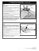
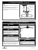
3. Ceiling Fan Assembly 3.13 (Continued) 1/2-INCH The fan comes with black and white leads that are 80-inches long. BLACK WIRE Measure up approximately 6 to 9-inches above top of hanger ball/4.5” downrod assembly (Figure 13). WHITE WIRE 6 TO 9 INCHES Cut off excess leads and strip back insulation 1/2-inch from end of leads. HANGER BALL Figure 13 4. How to Hang Your Ceiling Fan ! WARNING ! WARNING CEILING The fan must be hung with at least 7' of clearance from floor to blades (Figure 14).
4. How to Hang Your Ceiling Fan ! WARNING The outlet box and joist must be securely mounted and capable of supporting at least 50 lbs. Use only a U.L. outlet box listed as “Acceptable for Fan Support of 22.7 kg. (50 lbs.) or less”. ! WARNING To reduce the risk of fire, electric shock, or personal injury, mount fan to outlet box marked “Acceptable for Fan Support of 22.7 kg. (50 lbs.) or less”, and use screws supplied with outlet box.
5. Light Kit Assembly Skip to Section 6.0 if not installing the supplied light kit. 5.1 Remove one of the three screws in the Light Kit Adapter and loosen the remaining two screws (Figure 17). REMOVE LIGHT KIT ADAPTER PAN HEAD SCREW Retain the screw for future use. Figure 17 5.2 Engage the fan motor 2-pin wire connector into the 2pin wire connector of the Light Kit Assembly (Figure 18). The connection is complete when you hear a soft click.
5.4 5. Light Kit Assembly (Continued) Place the shade into the opening of the Light Kit Adapter, aligning the three flat areas on the top edge of the shade with the three raised dimples on the Light Kit Adapter and turn the shade clockwise until it stops (Figure 20). NOTE: Periodically check that the shade is seated fully clockwise in the Light Kit Adapter. LIGHT KIT ADAPTER RAISED DIMPLES (3) SHADE FLAT AREA OF SHADE (3) ROTATE CLOCKWISE Figure 20 6.
6. Optional Installation No-Light Plate Assembly 6.3 (Continued) Disengage the fan motor assembly 2-pin wire connector from the 2-pin wire connector of the Light Kit Assembly (Figure 23). Store Light Kit Assembly in a safe location for future installation. REINSTALL LIGHT KIT ADAPTER PAN HEAD SCREW Reinstall the #6-32 x .375” pan head screw into the Light Kit Adapter. Securely tighten the three #6-32 x .375” pan head screws. FAN MOTOR ASSEMBLY 2-PIN CONNECTOR A spare Light Kit Assembly #6-32 x .
7. How to Wire Your Ceiling Fan If you feel that you do not have enough electrical wiring knowledge or experience, have your fan installed by a licensed electrician. ! WARNING GROUND CONDUCTOR SUPPLY To avoid possible electrical shock, be sure electricity is turned off at the main fuse box before wiring. NOTE: If you are not sure if the outlet box is grounded, contact a licensed electrician for advice, as it must be grounded for safe operation.
7.2 7. How to Wire Your Ceiling Fan (Continued) Securely connect the fan motor white wire to the supply white (neutral) wire using wire connector (supplied) (Figure 26). SUPPLY WHITE (NEUTRAL) LISTED WIRE CONNECTOR FAN MOTOR WHITE WIRE Figure 26 7.3 Securely connect the fan motor black wire to the supply black (hot) wire using wire connector (supplied) (Figure 27). SUPPLY BLACK (HOT) LISTED WIRE CONNECTOR FAN MOTOR BLACK WIRE Figure 27 7.
7.5 7. How to Wire Your Ceiling Fan (Continued) Screw the two threaded studs (supplied) into the tapped holes in the hanger bracket (Figure 29). THREADED STUDS (2) Figure 29 7.6 Lift the ceiling cover up to the threaded studs and turn until studs protrude through the holes in the ceiling cover (Figure 30). CEILING COVER Secure the ceiling cover in place by sliding lockwashers over the threaded studs and installing the two knurled knobs (supplied). (Figure 30).
8. Wall Control Installation 8.1 8.2 Preset Memory Feature: Your Emerson receiver is equipped with a preset memory feature. If the AC supply to the receiver is powered OFF through a wall switch, the control will remember the light intensity and fan speed. When the switch is turned back ON the light and fan will resume operation as they were prior to the switch being turned OFF. Your Emerson Ceiling Fan/Light Control consists of wall mounted transmitter and a receiver located inside the motor assembly.
8.5 8. Wall Control Installation (Continued) NOTE: Electric connections should be in accordance with the National Electrical Codes and all Local Codes. Before starting, disconnect power to the circuit at the fuse box or circuit breaker panel. This control is designed to operate only one ceiling fan Remove the faceplate and screws from the existing wall switch. Pull switch out from wall outlet box. Determine the “hot” wire and the “load” wire and disconnect these wires from existing control (Figure 32).
8. Wall Control Installation SINGLE-POLE INSTALLATION (One fan controlled by one wall control) (See Figure 34). HOT BLK FAN/LIGHT WALL CONTROL LOAD BLACK ! WARNING ! WARNING ! WARNING Turning off wall switch is not sufficient. To avoid possible electrical shock, be sure electricity is turned off at the main fuse or circuit breaker box before wiring.
3-WAY INSTALLATION (One fan controlled by two different wall controls) (See Figures 35 and 36). WARNING Turning off wall switch is not sufficient. To avoid possible electrical shock, be sure electricity is turned off at the main fuse or circuit breaker box before wiring. All wiring must be in accordance with National and Local codes and the ceiling fan must be properly grounded as a precaution against possible electrical shock.
8. Wall Control Installation 3-WAY WIRING DIAGRAM: NEW CONSTRUCTION STANDARD WIRING FOR EXISTING 3-WAY CONTROLS NOTE: Retrofit 3-way installations are likely to include two traveler wires between the two wall boxes. In new construction, only one traveler wire Is required (See Figure 36). EXISTING WALL CONTROL HOT BLK WARNING BLACK ! (Continued) Turning off wall switch is not sufficient.
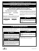
9. Programming the Receiver Operating Frequency & High Speed Conditioning of Fan Control -- Important - Read This Section Carefully and Follow the High Speed Conditioning Instructions Closely -9.2 PROGRAMMING THE RECEIVER OPERATING FREQUENCY & HIGH SPEED CONDITIONING OF FAN CONTROL If programming is unsuccessful, retry the previous instructions after cycling the wall control ON/OFF switch to restart the 1 minute programming time period.
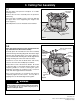
! 10. Using Your Ceiling Fan WARNING Fan installation must be completed, including the installation of the fan blades, before testing the wall control. POWER INDICATOR LIGHT LIGHT INTENSITY BUTTON AIRFLOW DIRECTION Your wall control has full control of your fan and light (Figure 37). NOTE: Prior to operation of the fan and light from the wall control, set the fan speed to HIGH (....) and turn the light ON ( ). FAN SPEED BUTTONS POWER BUTTON 10.
11. Maintenance IMPORTANT CARE INSTRUCTIONS for your Ceiling Fan ! WARNING ! WARNING Do not use water when cleaning your ceiling fan. It could damage the motor or the blades and create the possibility of an electrical shock. Periodic cleaning of your new ceiling fan is the only maintenance that is needed. When cleaning, use only a soft brush or lint free cloth to avoid scratching the finish. Abrasive cleaning agents are not required and should be avoided to prevent damage to finish. 12.
14. Light Kit LED Array Assembly Replacement ! WARNING To avoid possible electrical shock, be sure electricity is turned off at the main fuse box before wiring. NOTE: If you are not sure if the outlet box is grounded, contact a licensed electrician for advice, as it must be grounded for safe operation. Tools Needed One Phillips head screwdriver One stepladder ! WARNING Turning off wall switch is not sufficient.
14. Light Kit LED Array Assembly Replacement 14.4 (Continued) Disengage the fan motor assembly 2-pin wire connector from the 2-pin wire connector of the Light Kit Assembly (Figure 40). 14.5 Install new Light Kit Assembly by following the Section 5, Steps 5.2 through 5.4. Restore electricity and verify function of the Light Kit. FAN MOTOR ASSEMBLY 2-PIN CONNECTOR LIGHT KIT ASSEMBLY 2-PIN CONNECTOR Figure 40 15. Light Kit LED Driver Replacement The Light Kit Driver is located in the motor assembly.
15. Light Kit LED Driver Replacement 15.2 Remove the two knurled knobs and lockwashers from the threaded studs. Retain the hardware for future reinstallation (Figure 41). (Continued) CEILING COVER Slide the ceiling cover downward to rest on top the motor housing. THREADED STUDS (2) LOCKWASHERS (2) KNURLED KNOBS (2) Figure 41 15.3 Removal of the Ceiling Fan Wires, See Section 7, Reverse Steps 7.4 through 7.1.
15.5 15. Light Kit LED Driver Replacement NOTE: You may need help of an assistant to hold the ceiling cover, coupler cover and upper motor cover up and away from the motor housing, while performing the following steps. Slide the motor coupler cover up the downrod to access the top of the motor housing (Figure 44). (Continued) COUPLER COVER UPPER MOTOR COVER Figure 44 15.6 Remove the hairpin clip from the clevis pin. Remove the clevis pin from the downrod (Figure 45). MOTOR COUPLING 4.
15.8 15. Light Kit LED Driver Replacement MOTOR DC POWER CONNECTOR Squeeze and unclip the motor AC power connector from the Light Kit LED Driver connector (Figure 47). (Continued) LIGHT KIT LED DRIVER DC POWER CONNECTOR LIGHT KIT LED DRIVER Squeeze and unclip the motor DC power connector from the Light Kit LED Driver connector (Figure 47). MOTOR AC POWER CONNECTOR LIGHT KIT LED DRIVER AC POWER CONNECTOR Figure 47 15.
15. Light Kit LED Driver Replacement 15.11 MOTOR DC POWER CONNECTOR Reconnect the motor AC power connector to the Light Kit LED Driver connector (Figure 50). (Continued) LIGHT KIT LED DRIVER DC POWER CONNECTOR NEW LIGHT KIT LED DRIVER Reconnect the motor DC power connector to the Light Kit LED Driver connector (Figure 50). MOTOR AC POWER CONNECTOR LIGHT KIT LED DRIVER AC POWER CONNECTOR Figure 50 15.12 Replace the upper motor cover by reassembling the three screws previously removed in Step 15.7.
16. Repair Parts PARTS BAG 1 4 2 5 6 13 3 5 7 8 9 14 6 7 9 8 10 10 11 12 21 15 10 16 17 18 11 11 20 22 19 32 ETL Model No.
16. Repair Parts Listing Model Numbers Key No. Description CF860BQ00 CF860PT00 CF860WW00 761655- 19 761655-101 761655-0 1 2 3 Hanger Ball Assembly, Consisting of: Hanger Bracket (1) Hanger Ball (1) 4.5” Downrod (1) — — — — — — — — — * 4 5 6 7 8 9 10 11 12 Parts Bag Containing: Wire Connectors (5) Studs, Threaded, #8-32 x 1-1/4” (2) Lockwashers, External Tooth, #8 (2) Knobs, Knurled, #8-32 (2) Pin, Clevis (1) Clip, Hairpin (1) Washer Head Screw, #8-32 x .50” (16) Pan Head Screw, #6-32 x .
17. Troubleshooting ! WARNING FOR YOUR OWN SAFETY TURN OFF POWER AT FUSE BOX OR CIRCUIT BREAKER BEFORE TROUBLESHOOTING YOUR FAN. TROUBLE 1. Fan will not start. SUGGESTED REMEDY PROBABLE CAUSE 1. Check the electrical connections at the ceiling cover. 1. Loose electrical connections in the ceiling cover. ! WARNING Make sure main power is turned OFF. 2. Fan sounds noisy. 1. Blades not attached to fan. 1. Attach blades to fan before operating. 2.
Emerson Air Comfort Ceiling Fan Limited Warranty What The Limited Warranty Covers: This limited warranty is offered by Air Comfort Products division of Emerson Electric Co. ("Emerson" "we" or "us") located at the address stated below to the original retail purchaser ("you" or "your") of an Emerson Air Comfort Ceiling Fan product ("Emerson Ceiling Fan") and covers the motor and the other components and accessories of the Emerson Ceiling Fan against all defects in workmanship and materials.
SERIAL NUMBER: DATE CODE: The serial number of this fan can be found on the nameplate on top of the fan housing. The date code can be found on the carton and on top of the fan housing, stamped in ink on a white label. You should record this data above and keep it in a safe place for future use. Air Comfort Products DIVISION OF EmErSON ElEctrIc cO. 8100 W. Florissant • St. louis, mO 63136 Questions, problems, missing parts: Before returning to the store call Emerson Electric Customer Service 8 a.m.
CONTEMPORÁNEO LEA Y GUARDE ESTAS INSTRUCCIONES LURAY ECO™ Manual del usuario para ventiladores de techo de 60 pulgadas para lugares húmedos CF860BQ00 – Negro barbacoa CF860PT00 – Platino CF860WW00 – Blanco electrodoméstico Números de modelo Peso neto: 20,02 lb. Preguntas, problemas, piezas faltantes: Antes de devolver el producto a la tienda, llame al Servicio al Cliente de Emerson Electric — 8 a.m. a 6 p.m., Hora del Este, lunes a viernes • Français - page 73 1-800-654-3545 No.
Índice Sección Página Instrucciones de seguridad . . . . . . . . . . . . . . . . . . . . . . . . . . . . . . . . . . . . 38 1. Instrucciones de desempaquetado . . . . . . . . . . . . . . . . . . . . . . . . . . 39-40 2. Requisitos eléctricos . . . . . . . . . . . . . . . . . . . . . . . . . . . . . . . . . . . . . . . 40 3. Ensamblaje del ventilador de techo . . . . . . . . . . . . . . . . . . . . . . . . . 41-46 4. Cómo colgar su ventilador de techo . . . . . . . . . . . . . . . . . . . . . . . . 46-47 5.
1. Instrucciones de desempaquetado ADVERTENCIA CONTENIDO DEL PAQUETE 1-800-654-3545 Pieza No instale ni utilice el ventilador si alguna pieza está dañada o falta. Llame gratis para obtener piezas de repuesto: A B C ADVERTENCIA D E F G H I J K Este producto está diseñado para utilizar únicamente las piezas suministradas con este producto y/o los accesorios diseñados específicamente por Emerson Electric Co. para utilizarse con este producto.
1. Instrucciones de desempaquetado (continuación) Este manual está diseñado para que usted pueda ensamblar, instalar, utilizar y mantener su ventilador de techo de la manera más fácil posible ESTE VENTILADOR ES ADECUADO PARA LUGARES HÚMEDOS, TALES COMO PORCHES CUBIERTOS, PATIOS CUBIERTOS Y TERRAZAS CUBIERTAS. CUALQUIER LUGAR QUE ESTE CUBIERTO POR UN TEJADO. UTILÍCELO SÓLO CON KITS DE LUZ MARCADOS COMO ADECUADOS PARA USO EN LUGARES HÚMEDOS.
3. Ensamblaje del ventilador de techo 3.1 ENSAMBLAJE DEL MOTOR DEL FAN MOTOR VENTILADOR ASSEMBLY Voltee la almohadilla de espuma superior y colóquela sobre una superficie de trabajo estable. Saque el ensamblaje del motor del ventilador de la bolsa protectora de plástico. Coloque el ensamblaje del motor del ventilador encima de la almohadilla de espuma, de manera que la cubierta superior del motor soporte el peso del motor (Figura 1). Esto permitirá el acceso para instalar las paletas.
3. Ensamblaje del ventilador de techo (continuación) 3.3 ROTE EN EL SENTIDO DE LAS AGUJAS DEL RELOJ ROTATE CLOCKWISE Retire uno de los tres tornillos de cabeza troncocónica del núcleo del ensamblaje del motor y retenga el tornillo para uso futuro. Afloje los dos tornillos restantes (Figura 3).
3. Ensamblaje del ventilador de techo (continuación) 3.5 BLADE SCREWS TORNILLOS PARA PALETA (2 por (2 perensamblaje blade de paleta) assembly) NOTA: La instalación de la paleta se habrá completado después de este paso: Alinee los dos agujeros de lengüeta de una paleta con los agujeros roscados del motor e instale un tornillo con cabeza de arandela en cada agujero (Figura 5). ENSAMBLAJE BLADE DE PALETA (3) (3) ASSEMBLY Apriete flojamente cada tornillo en la orejeta del motor.
3. Ensamblaje del ventilador de techo (continuación) 3.7 DE CONEXIÓN DEL MOTOR DE 80 PULGADAS (NO TRENZADOS) DOS CABLES TWO 80" MOTOR LEADS (UNTWISTED) Separe, desenrede y desanude los dos cables de conexión del motor de 80 pulgadas. Encamine los dos cables de conexión del motor a través de la varilla descendente de 4,5 pulgadas (Figura 7). VARILLA DESCENDENTE 4.5" DOWNROD DE 4.5 PULG. Figura 7 3.
3. Ensamblaje del ventilador de techo (continuación) 3.10 Asegúrese de que el aro de refuerzo esté instalado apropiadamente sobre la cubierta del acoplador y luego deslice dicha cubierta sobre la varilla descendente hasta que descanse sobre la carcasa del motor (Figura 10). VARILLA DESCENDENTE 4.5" DOWNROD DE 4.5 PULG. ARO DE REFUERZO COUPLER DE LACOVER CUBIERTA GROMMET DEL ACOPLAMIENTO DEL CUBIERTA COUPLER ACOPLADOR COVER Figura 10 3.
3. Ensamblaje del ventilador de techo (continuación) 3.13 1/21/2-INCH PULGADA El ventilador viene con cables de conexión de color negro y blanco que tienen 80 pulgadas de longitud. CABLE NEGRO BLACK WIRE Mida hacia arriba aproximadamente de 6 a 9 pulgadas por encima de la parte superior del ensamblaje de esfera de suspensión/varilla descendente de 4,5 pulgadas (Figura 13). CABLE BLANCO WHITE WIRE 6 6TO a99 INCHES PULG.
4. Cómo colgar su ventilador de techo (continuación) ADVERTENCIA La caja de tomacorriente y la viga deben estar montadas de manera segura y ser capaces de soportar por lo menos 50 lb. Utilice únicamente una caja de tomacorriente U.L. listada con las palabras “Acceptable for Fan Support of 22.7 kg. (50 lbs.) or less” (Aceptable para soportar ventiladores de 22,7 kg (50 lb) o menos).
5. Ensamblaje del kit de iluminación Vaya a la Sección 6.0 si no está instalando el kit de iluminación suministrado. 5.1 Retire uno de los tres tornillos del adaptador para el kit de iluminación y afloje los dos tornillos restantes (Figura 17). Retenga el tornillo para uso futuro. EL TORNILLO RETIRE REMOVE LIGHT DEKIT CABEZA TRONCOCÓNICA ADAPTER PAN ADAPTADOR DEL HEAD SCREW PARA EL KIT DE ILUMINACIÓN Figura 17 5.
5. Ensamblaje del kit de iluminación (continuación) 5.4 Coloque la pantalla dentro de la abertura del adaptador para el kit de iluminación, alineando las tres áreas planas del borde superior de la pantalla con los tres hoyuelos en relieve ubicados en el adaptador para el kit de iluminación, y gire la pantalla en el sentido de las agujas de reloj hasta que se detenga (Figura 20).
6. Instalación opcional del ensamblaje del plato sin luz (continuación) 6.3 Desacople el conector de cables de 2 pines del ensamblaje del motor, separándolo del conector de cables de 2 pines del ensamblaje del kit de iluminación (Figura 23). Guarde el ensamblaje del kit de iluminación en un lugar seguro para instalarlo en el futuro. Reinstale el tornillo de cabeza troncocónica núm. 6-32 x 0,375 pulgadas en el adaptador para el kit de iluminación.
7. Cómo cablear su ventilador de techo Si le parece que no tiene suficientes conocimientos o experiencia en cableado eléctrico, haga que un electricista con licencia instale su ventilador. ADVERTENCIA CABLE DE SUMINISTRO GROUND DEL CONDUCTOR DE CONDUCTOR SUPPLY CONEXIÓN A TIERRA Para evitar posibles descargas eléctricas, asegúrese de que la electricidad esté desconectada en la caja de fusibles principal antes de realizar el cableado.
7.Cómo colgar su ventilador de techo (continuación) 7.2 Conecte de manera segura el cable blanco del motor del ventilador al cable blanco de suministro (neutro) utilizando el conector de cables suministrado (Figura 26). CABLE BLANCO DE SUMINISTRO SUPPLY WHITE (NEUTRO) (NEUTRAL) LISTED WIRE CONECTOR DE CONNECTOR CABLES LISTADO CABLE BLANCO DEL MOTOR FAN MOTOR DEL VENTILADOR WHITE WIRE Figura 26 7.
7.Cómo colgar su ventilador de techo (continuación) 7.5 Enrosque los dos espárragos roscados (suministrados) en los agujeros roscados del soporte de suspensión (Figura 29). ESPÁRRAGOS THREADED ROSCADOS STUDS (2)(2) Figura 29 7.6 Levante la cubierta del techo hasta los espárragos roscados y gírela hasta que dichos espárragos sobresalgan a través de los agujeros ubicados en la cubierta del techo (Figura 30).
8. Instalación del control de pared 8.1 8.2 Su control del ventilador de techo y luz Emerson consiste en un transmisor montado en la pared y un receptor ubicado dentro del ensamblaje del motor. El control está diseñado para operar remotamente la velocidad, la intensidad de la luz y el sentido de rotación del ventilador de techo. Función de memoria preestablecida: Su receptor Emerson está equipado con una función de memoria preestablecida.
8. Instalación del control de pared (continuación) 8.5 Este control está designado para operar sólo un ventilador de techo. NOTA: Las conexiones eléctricas deberán cumplir con los Códigos Eléctricos Nacionales y los Códigos Locales. Antes de comenzar, desconecte la alimentación al circuito en la caja de fusibles o en el panel de cortacircuitos. Retire la placa frontal y los tornillos del interruptor de pared existente. Jale el interruptor hasta sacarlo de la caja de tomacorriente de la pared.
8. Instalación del control de pared (continuación) ADVERTENCIA INSTALACIÓN UNIPOLAR (Un ventilador controlado por un control de pared) (Vea la Figura 34). CON CORRIENTE HOT NGR BLK No basta con poner el interruptor de pared en la posición de apagado. Para evitar una posible descarga eléctrica, asegúrese de que la electricidad esté desconectada en la caja de fusibles principal antes de realizar el cableado.
8. Instalación del control de pared (continuación) (Un ventilador controlado por dos controles de pared diferentes) (consulte las Figuras 35 y 36.) ADVERTENCIA CONTROL DE FAN/LIGHT PARED DEL WALL Y VENTILADOR CONTROL LA LUZ NEGRO BLACK No basta con poner el interruptor de pared en la posición de apagado. Para evitar una posible descarga eléctrica, asegúrese de que la electricidad esté desconectada en la caja de fusibles principal antes de realizar el cableado.
8. Instalación del control de pared (continuación) DIAGRAMA DE CABLEADO DE 3 VÍAS: CONSTRUCCIÓN NUEVA CABLEADO ESTÁNDAR PARA CONTROLES DE 3 VÍAS EXISTENTES NOTA: Es probable que las instalaciones de 3 vías reconvertidas incluyan dos cables conmutables entre las dos cajas de pared. En el caso de una construcción nueva, sólo se requiere un cable conmutable (vea la Figura 36).
9. Programación de la frecuencia de operación del receptor y acondicionamiento de alta velocidad del control del ventilador – Importante: Lea detenidamente esta sección y siga minuciosamente las instrucciones de acondicionamiento de alta velocidad – PROGRAMACION DE LA FRECUENCIA DE OPERACION DEL RECEPTOR Y ACONDICIONAMIENTO DE ALTA VELOCIDAD DEL CONTROL DEL VENTILADOR 9.
10. Utilización del ventilador de techo ADVERTENCIA Se debe completar la instalación del ventilador, incluyendo la instalación de las paletas del ventilador, antes de probar el control remoto. POWER LUZ INDICADORA DE INDICATOR ALIMENTACIÓN LIGHT SENTIDO DE BOTÓN LIGHTDE INTENSIDAD INTENSITY DE LA LUZ AIRFLOW CIRCULACIÓN DEL AIRE DIRECTION El control de pared tiene control completo del ventilador y la luz (Figura 37).
11. Mantenimiento ADVERTENCIA INSTRUCCIONES DE CUIDADO IMPORTANTES para su ventilador de techo No use agua cuando limpie su ventilador de techo. El agua podría dañar el motor o las paletas y crear la posibilidad de una descarga eléctrica. La limpieza periódica de su nuevo ventilador de techo es el único mantenimiento que se necesita. Cuando limpie el ventilador, utilice un cepillo blando o un paño libre de pelusa para evitar rasguñar el acabado.
14. Reemplazo del ensamblaje del conjunto de luces LED del kit de iluminación ADVERTENCIA ADVERTENCIA Para evitar posibles descargas eléctricas, asegúrese de que la electricidad esté desconectada en la caja de fusibles principal antes de realizar el cableado. NOTA: Si no está seguro si la caja de tomacorriente está conectada a tierra, contacte a un electricista con licencia para obtener asesoramiento, ya que dicha caja debe estar conectada a tierra para que el funcionamiento sea seguro.
14. Reemplazo del ensamblaje del conjunto de luces LED del kit de iluminación (continuación) 14.4 Desacople el conector de cables de 2 pines del ensamblaje del motor del ventilador, separándolo del conector de cables de 2 pines del ensamblaje del kit de iluminación (Figura 40). 14.5 Instale el ensamblaje del kit de iluminación nuevo siguiendo la Sección 5, Pasos 5.2 a 5.4.
15. Reemplazo del accionador LED del kit de iluminación (cont.) 15.2 Retire los dos pomos estriados y las dos arandelas de seguridad de los espárragos roscados. Retenga los herrajes para su reinstalación futura (Figura 41). CUBIERTA CEILING DEL TECHO COVER Deslice hacia abajo la cubierta del techo hasta que quede apoyada sobre la carcasa del motor. ESPÁRRAGOS THREADED ROSCADOS (2) STUDS (2) ARANDELAS DE SEGURIDAD LOCKWASHERS (2)(2) KNURLED POMOS KNOBS (2) ESTRIADOS (2) Figura 41 15.
15. Reemplazo del accionador LED del kit de iluminación (cont.) 15.5 CUBIERTA DEL COUPLER ACOPLADOR COVER NOTA: Es posible que necesite la asistencia de un ayudante para sujetar la cubierta del techo, la cubierta del acoplador y la cubierta superior del motor hacia arriba y alejándolas de la carcasa del motor, mientras realiza los siguientes pasos. Deslice la cubierta del acoplador del motor hacia arriba por la varilla descendente para acceder a la parte superior de la carcasa del motor (Figura 44).
15. Reemplazo del accionador LED del kit de iluminación (cont.) 15.
15. Reemplazo del accionador LED del kit de iluminación (cont.) 15.11 CONECTOR MOTORDE DCALIMENTACIÓN POWER DE CC DEL MOTOR Reconecte el conector de alimentación de CA del motor al conector del accionador LED del kit de iluminación (Figura 50). CONNECTOR Reconecte el conector de alimentación de CC del motor al conector del accionador LED del kit de iluminación (Figura 50).
16. Piezas de repuesto PARTS BAG BOLSA DE PIEZAS 1 4 2 5 6 13 3 5 7 8 9 14 6 7 9 8 10 10 11 12 21 15 10 16 17 18 11 11 20 22 19 68 No.
16. Lista de piezas de repuesto Números de modelo No. de clave Descripción CF860BQ00 CF860PT00 CF860WW00 1 2 3 Ensamblaje de la esfera de suspensión, que consiste en: Soporte de suspensión (1) Esfera de suspensión (1) Varilla descendente de 4,5 pulgadas (1) 761655- 19 — — 761655-101 — — 761655-0 — — * Bolsa de piezas que contiene: 764748-BLOX 764748-CHRM 764748-WW 4 Conectores de cables (5) — — — 5 Espárragos roscados #8-32 x 1-1/4 pulg.
17. Resolución de problemas ADVERTENCIA PARA SU PROPIA SEGURIDAD, DESCONECTE LA ALIMENTACIÓN ELÉCTRICA EN LA CAJA DE FUSIBLES O EL CORTACIRCUITO ANTES DE RESOLVER PROBLEMAS EN SU VENTILADOR PROBLEMA 1. El ventilador no arranca. CAUSA PROBABLE REMEDIO SUGERIDO 1. Conexiones eléctricas flojas en la cubierta del techo. 1. Compruebe las conexiones eléctricas en la cubierta del techo. ADVERTENCIA Asegúrese de que la alimentación eléctrica principal esté APAGADA. 2. El ventilador hace ruido. 1.
Garantía limitada para ventiladores de techo de Emerson Air Comfort Lo que la garantía limitada cubre: Esta garantía limitada es ofrecida por la división Air Comfort Products de Emerson Electric Co.
NÚMERO DE SERIE:____________________________________ CÓDIGO DE FECHA:__________________________________ El número de serie de este ventilador se puede encontrar en la placa de especificaciones ubicada encima de la carcasa del ventilador. El código de fecha se puede encontrar en la caja de cartón y encima de la carcasa del ventilador, estampado en tinta en una etiqueta blanca. Usted deberá anotar esta fecha arriba y guardarla en un lugar seguro para uso futuro.
CONTEMPORAIN LISEZ ET CONSERVEZ CES INSTRUCTIONS LURAY ECO™ Mode d’emploi du ventilateur de plafond de 60 po pour environnement humide CF860BQ00 – Noir barbecue CF860PT00 – Platine CF860WW00 – Blanc électroménager Numéros des modèles Poids net : 20,02 lbs Questions, problèmes, pièces manquantes : Avant de retourner un produit au magasin, veuillez téléphoner au Emerson Electric Customer Service de 8h00 à 18h00, Heure de l’Est, du lundi au vendredi Pièce N° F40BP75150000 Révision : 160503 1-800-654-
Table des matières Section Page Section Consignes de sécurité . . . . . . . . . . . . . . . . . . . . . . . . . . . . . . . . . . . . . . . . .74 1. Instructions pour le déballage . . . . . . . . . . . . . . . . . . . . . . . . . . . . . . .75-76 2. Alimentation électrique . . . . . . . . . . . . . . . . . . . . . . . . . . . . . . . . . . . . . . .76 3. Assemblage du ventilateur de plafond . . . . . . . . . . . . . . . . . . . . . . . .77-82 4. Comment suspendre votre ventilateur de plafond . . . . . .
1. Instructions pour le déballage AVERTISSEMENT CONTENU DU PAQUET 1-800-654-3545 Pièce Il ne faut pas installer le ventilateur si une pièce quelconque est endommagée ou manquante.
1. Instructions pour le déballage (suite) Ce mode d’emploi est conçu pour vous permettre d’assembler, d’installer, d’utiliser et d’entretenir votre ventilateur de plafond aussi facilement que possible CE VENTILATEUR EST APPROPRIÉ POUR EMPLOI DANS DES ENDROITS HUMIDES TELS QUE DES VÉRANDAS, DES PLATEFORMES ET DES PATIOS COUVERTS. PARTOUT OÙ IL Y A UN TOIT AU-DESSUS. NE L’UTILISEZ QU’AVEC DES SYSTÈMES D’ÉCLAIRAGE INDIQUÉS COMME ÉTANT APPROPRIÉS POUR UN EMPLOI DANS DES ENDROITS HUMIDES.
3. Assemblage du ventilateur de plafond 3.1 ENSEMBLE DE MOTEUR DU FAN MOTOR VENTILATEUR ASSEMBLY Retournez le coussinet de mousse supérieur et placez sur une surface de travail stable. Retirez l’ensemble de ventilateur du sac de protection en plastique. Placez l’ensemble de moteur du ventilateur sur le dessus du coussinet de mousse de telle façon que le carter supérieur du moteur supporte le poids du moteur (Figure 1). Ceci donnera accès pour permettre d’installer les pales.
3. Assemblage du ventilateur de plafond (suite) 3.3 FAIRE TOURNER DANS LE SENS DES AIGUILLES D’UNE MONTRE ROTATE CLOCKWISE Retirez l’une des trois vis à tête cylindrique bombée du moyeu de l’ensemble de moteur, mettez la vis de côté en vue de réutilisation ultérieurement et desserrez les deux autres vis (Figure 3).
3. Assemblage du ventilateur de plafond (suite) 3.5 DE FIXATION DES PALES VIS BLADE SCREWS ensemble (2 (2par per bladede pale) REMARQUE : L’installation de la pale sera achevée à la fin de cette étape du processus : assembly) Alignez les deux trous des languettes de fixation des pales d’une pale sur les trous filetés du moteur et installez une vis à tête à embase dans chaque trou (Figure 5). ENSEMBLE BLADE PALE (3) DE ASSEMBLY (3) Serrez partiellement chaque vis dans l’oreille du moteur.
3. Assemblage du ventilateur de plafond (suite) 3.7 DE MOTEUR DE 80(UNTWISTED) po (DÉTORSADÉS) DEUX TWOCÂBLES 80" MOTOR LEADS Séparez, détordez et désentortillez les deux conducteurs du moteur de 80 po. Acheminez les deux câbles du moteur à travers la tige de suspension descendante de 4,5 po (Figure 7). TIGE SUSPENSION 4.5" DE DOWNROD DESCENDANTE DE 4,5 po Figure 7 3.
3. Assemblage du ventilateur de plafond (suite) 3.10 Assurez-vous que l’œillet est installé correctement dans le cache du coupleur, puis faites glisser le cache du coupleur sur la tige de suspension descendante jusqu’à ce qu’il repose sur le boîtier du moteur (Figure 10). TIGE SUSPENSION 4.5" DE DOWNROD DESCENDANTE DE 4,5 po ŒILLET DU CACHE DU COUPLER COVER DE COUPLAGE DISPOSITIF GROMMET COUPLER CACHE DU COUPLEUR COVER Figure 10 3.
3. Assemblage du ventilateur de plafond (suite) 3.13 1/2 po (1,27 cm) 1/2-INCH Le ventilateur est fourni avec des fils noir et blanc mesurant 80 po de long. FIL NOIR BLACK WIRE Mesurez jusqu’à environ 6 à 9 po (15 à 23 cm) au-dessus du dessus de l’ensemble de rotule de la tige de suspension/tige descendante de 4,5 po (11,25 cm) (Figure 13).
4. Comment suspendre votre ventilateur de plafond (suite) AVERTISSEMENT Le boîtier de prises de courant et la solive doivent être installés de façon sécurisée et être capables de supporter sans problème au moins 50 livres (22,7 kg). Utilisez seulement des boîtiers de prises de courant homologués U.L. comportant l’indication suivante : « Acceptable for Fan Support of 22.7 kg. (50 lbs.) or less » (Acceptable pour support de ventilateur de 22,7 kg (50 lbs) ou moins).
5. Ensemble de kit de luminaire Passez directement à la Section 6.0 si vous n’installez pas le kit de luminaire fourni. 5.1 Retirez l’une des trois vis dans l’adaptateur du kit de luminaire et desserrez les deux autres vis (Figure 17). Mettez la vis de côté en vue de réutilisation ultérieurement. LA VIS À TÊTE RETIRER REMOVE LIGHT BOMBÉE CYLINDRIQUE KIT ADAPTER PAN DE L’ADAPTATEUR HEAD SCREW DU KIT DE LUMINAIRE Figure 17 5.
5. Ensemble de kit de luminaire (suite) 5.4 Placez l’abat-jour dans l’ouverture de l’adaptateur du kit de luminaire en alignant les trois zones plates sur le bord supérieur de l’abat-jour sur les trois excroissances de l’adaptateur du kit de luminaire et faites tourner l’abat-jour dans le sens des aiguilles d’une montre jusqu’à ce qu’il ne puisse plus continuer à tourner (Figure 20).
6. Installation facultative de l’ensemble de plaque de recouvrement en l’absence de luminaire (suite) 6.3 Désengagez le capuchon de connexion à 2 broches de l’ensemble de moteur du ventilateur du capuchon de connexion à 2 broches de l’ensemble de kit de luminaire (Figure 23). Rangez l’ensemble de kit de luminaire en lieu sûr en vue de réinstallation à l’avenir. Réinstallez la vis à tête cylindrique bombée N° 6-32 x 0,375 po dans l’adaptateur du kit de luminaire.
7. Comment effectuer le câblage pour raccorder votre ventilateur de plafond Si vous pensez que vous n’avez pas d’expérience ou de connaissances suffisantes en matière de câblage, demandez à un électricien agréé de réaliser l’installation de votre ventilateur. AVERTISSEMENT ALIMENTATION DU GROUND CONDUCTEUR DE TERRE CONDUCTOR SUPPLY Pour éviter tout risque de choc électrique, assurez-vous que l’alimentation électrique est coupée au niveau du boîtier des fusibles avant d’effectuer le câblage.
7. Comment effectuer le câblage pour raccorder votre ventilateur de plafond (suite) 7.2 Connectez solidement le fil blanc provenant du moteur du ventilateur au fil blanc (neutre) de l’alimentation en utilisant un capuchon de connexion de fils fourni (Figure 26). FIL D’ALIMENTATION BLANC (NEUTRE) SUPPLY WHITE (NEUTRAL) DE CAPUCHON LISTED WIRE CONNEXION DE CONNECTOR LISTÉS FILS FIL BLANC DU MOTEUR FAN MOTOR VENTILATEUR DU WHITE WIRE Figure 26 7.
7. Comment effectuer le câblage pour raccorder votre ventilateur de plafond (suite) 7.5 Vissez les deux goujons filetés (fournis) dans les trous taraudés du support de suspension (Figure 29). GOUJON THREADED FILETÉ STUDS (2)(2) Figure 29 7.6 Soulevez la monture de plafond jusqu’au niveau des goujons filetés et faites la tourner jusqu’à ce que les goujons dépassent des trous de la monture de plafond (Figure 30).
8. Installation de la commande murale 8.1 8.2 Votre commande du ventilateur de plafond/luminaire Emerson consiste en un transmetteur monté sur un mur et un récepteur qui est monté sous le cache du ventilateur de plafond. La télécommande est conçue de façon à vous permettre de contrôler à distance la vitesse et le sens de rotation de votre ventilateur de plafond, ainsi que l’intensité de l’éclairage.
8. Installation de la commande murale (suite) 8.5 Cette commande n’est conçue que pour faire fonctionner un seul ventilateur de plafond. REMARQUE : Tout le câblage électrique doit être conforme aux dispositions du Code national d’électricité et des codes d’électricité locaux. Avant de commencer, coupez l’alimentation au circuit au niveau du coffret à fusibles ou du panneau à disjoncteurs. Retirez la plaque de recouvrement et les vis de l’interrupteur mural existant.
8. Installation de la commande murale (suite) AVERTISSEMENT INSTALLATION UNIPOLAIRE (Un ventilateur commandé par une commande murale) (Voir Figure 34 SOUS TENSION HOT NOIR BLK Éteindre l’interrupteur mural ne suffit pas. Pour éviter tout choc électrique éventuel, assurez-vous que l’alimentation électrique est coupée au niveau du boîtier des fusibles avant d’effectuer le câblage. Tout le câblage doit être conforme aux dispositions du Code national d’électricité et des codes d’électricité locaux.
8. Installation de la commande murale (suite) (Un ventilateur contrôlé depuis deux commandes murales différentes) (Voir Figures 35 et 36 HOT NOIR BLK AVERTISSEMENT COMMANDE FAN/LIGHT MURALE DU WALL VENTILATEUR/ CONTROL LUMINAIRE NOIR BLACK Éteindre l’interrupteur mural ne suffit pas. Pour éviter tout choc électrique éventuel, assurez-vous que l’alimentation électrique est coupée au niveau du boîtier des fusibles avant d’effectuer le câblage.
8. Installation de la commande murale (suite) SCHÉMA DE CÂBLAGE POUR INSTALLATION AVEC DOUBLE COMMANDE : CONSTRUCTION NEUVE CÂBLAGE STANDARD POUR LES INSTALLATIONS EXISTANTES AVEC DOUBLE COMMANDE REMARQUE : Les installations avec double commande ayant été modifiées incluent probablement deux fils itinérants entre les deux boîtiers muraux. Dans les constructions neuves, seul un fil itinérant est nécessaire (Voir Figure 36).
9. Programmation de la fréquence de fonctionnement du récepteur & conditionnement à haute vitesse de la commande du ventilateur – Important – Lire attentivement la présente section et suivre à la lettre les instructions sur le conditionnement à haute vitesse – PROGRAMMATION DE LA FREQUENCE DE FONCTIONNEMENT DU RECEPTEUR & CONDITIONNEMENT À HAUTE VITESSE DE LA COMMANDE DU VENTILATEUR 9.
10. Utilisation de votre ventilateur de plafond AVERTISSEMENT L’utilisation de toute autre commande qui ne serait pas spécifiquement approuvée pour ce ventilateur pourrait entraîner un incendie, un choc et une blessure. POWER VOYANT INDICATEUR INDICATOR MISE SOUS DE LIGHT TENSION BOUTON DE LIGHT DE CONTRÔLE L’INTENSITÉ INTENSITY LUMINEUSE BUTTON SENS DE AIRFLOW CIRCULATION DE L’AIR DIRECTION C’est votre commande murale qui contrôle totalement votre ventilateur, ainsi que le luminaire (Figure 37).
11. Maintenance AVERTISSEMENT INSTRUCTIONS IMPORTANTES CONCERNANT L’ENTRETIEN de votre ventilateur de plafond N’utilisez pas d’eau lorsque vous nettoyez votre ventilateur de plafond car ceci pourrait endommager le moteur ou les pales et vous exposer à un risque de choc électrique. Pour maintenir votre ventilateur de plafond en bon état, il vous suffit simplement de le nettoyer périodiquement. Lorsque vous le nettoyez, utilisez une brosse douce ou un tissu non pelucheux pour éviter de rayer la finition.
14. Remplacement de l’ensemble de matrice de DEL du kit de luminaire AVERTISSEMENT AVERTISSEMENT Pour ne pas risquer de recevoir un choc électrique, vérifiez que le courant est coupé au niveau du boîtier de fusibles avant de commencer le câblage. REMARQUE : Si vous ne savez pas si le coffret de prises de courant est mis à la terre, contactez un électricien professionnel pour lui demander conseil, étant donné qu’il est nécessaire qu’il soit mis à la terre pour assurer un fonctionnement sans danger.
14. Remplacement de l’ensemble de matrice de DEL du kit de luminaire (suite) 14.4 Désengagez le capuchon de connexion à 2 broches de l’ensemble de moteur du ventilateur du capuchon de connexion à 2 broches de l’ensemble de kit de luminaire (Figure 40). 14.5 Installez le nouvel ensemble de kit de luminaire en suivant les instructions de la Section 5, étapes 5.2 à 5.4. Rétablissez l’électricité et vérifiez le fonctionnement du kit de luminaire.
15. Remplacement du circuit de commande de DEL du kit de luminaire (suite) 15.2 Retirez les deux boutons moletés et les rondelles de blocage des goujons filetés. Conservez le petit matériel de fixation en vue de réinstallation ultérieure (Figure 41). CACHE POUR CEILING PLAFOND COVER Faites glisser la monture de plafond vers le bas pour qu’elle reposer sur le dessus du boîtier du moteur.
15. Remplacement du circuit de commande de DEL du kit de luminaire (suite) 15.5 DU CACHE COUPLER COUPLEUR COVER REMARQUE : Vous aurez peut-être besoin d’un assistant pour soulever et tenir la monture de plafond, le cache du coupleur et le carter supérieur du moteur à distance du boîtier du moteur pendant que vous accomplirez les actions suivantes.
15. Remplacement du circuit de commande de DEL du kit de luminaire (suite) 15.8 Comprimez et détachez le connecteur d’alimentation c.a. du moteur du connecteur du circuit de commande des DEL du kit de luminaire (Figure 47). MOTOR DCD’ALIMENTATION POWER CONNECTEUR c.c. DU MOTEUR CONNECTOR Comprimez et détachez le connecteur d’alimentation c.c. du moteur du connecteur du circuit de commande des DEL du kit de luminaire (Figure 47). CONNECTEUR D’ALIMENTATION c.c.
15. Remplacement du circuit de commande de DEL du kit de luminaire (suite) 15.11 Reconnectez le connecteur d’alimentation c.a. du moteur au connecteur du circuit de commande des DEL du kit de luminaire (Figure 50). D’ALIMENTATION CONNECTEUR MOTOR DC POWER DU MOTEUR c.c. CONNECTOR D’ALIMENTATION c.c.
16. Pièces de rechange PARTS BAG DE PIÈCES SAC 1 4 2 5 6 13 3 5 7 8 9 14 6 7 9 8 10 10 11 12 21 15 10 16 17 18 11 11 20 22 19 104 Modèle E.T.L.
16. Nomenclature des pièces de rechange Numéros de modèles Réf.
17. Identification des causes des problèmes AVERTISSEMENT POUR VOTRE SÉCURITÉ, METTEZ LE COFFRET À FUSIBLES OU LE DISJONCTEUR HORS TENSION AVANT DE TENTER D’IDENTIFIER LES PROBLÈMES POUVANT AFFECTER VOTRE VENTILATEUR. PROBLÈME 1. Le ventilateur ne démarre pas. CAUSE PROBABLE SOLUTION PROPOSÉE 1. Connexions électriques desserrées dans la monture de plafond. 1. Inspectez les connexions électriques dans la monture de plafond. AVERTISSEMENT Vérifiez au préalable que l’alimentation est coupée. 2.
Garantie limitée relative aux ventilateurs de plafond de la division Air Comfort d’Emerson Ce qui est couvert par la présente garantie limitée : La présente garantie limitée est offerte par la division Air Comfort Products d’Emerson Electric Co.
NUMÉRO DE SÉRIE :____________________________________ CODE DE DATE :___________________________________ Le numéro de série de ce ventilateur figure sur la plaque signalétique en haut du boîtier du ventilateur. Le code de date figure sur le carton et en haut du boîtier du ventilateur. Il est estampé à l’encre sur une étiquette blanche. Il faut enregistrer ces informations et les conserver en lieu sûr pour une utilisation future. Air Comfort Products DIVISION OF EmErSON ElEctrIc cO. 8100 W. Florissant • St.