
Instructions / Assembly

6
ETL Model No.: CF860
3. Ceiling Fan Assembly (Continued)
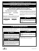
PARTIALLY
ASSEMBLED
FAN
LIGHT KIT
ADAPTER
UPPER MOTOR
COVER
Figure 4
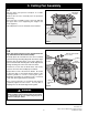
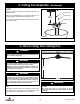
3.4
Grasp the motor by the light kit adapter and upper motor
cover, and carefully turn the partially assembled ceiling
fan over and place directly on top of the foam pad such
that the light kit adapter is supporting the weight of the fan.
The blades should be free to rotate. (Figure 4).
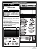
LIGHT KIT ADAPTER
ROTATE CLOCKWISE
MOTOR ASSEMBLY
HUB
PAN HEAD SCREW
Figure 3
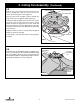
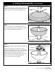
3.3
Remove one of the three pan head screws from the
motor assembly hub, retain the screw for future use.
L
oosen the remaining two screws (Figure 3).
Place the 2-pin motor assembly connector through the
l
arge center hole of the light kit adapter (Figure 3).
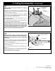
Position the light kit adapter key hole slots onto the two
loosened screw heads. Rotate the switch housing
adapter clockwise to engage the two screws. Verify that
the serrated washers are not trapped between the light
kit adapter and the motor hub. Reinstall the previously
removed screw.
Retighten all three screws to securely attach the light kit
adapter to the motor assembly.
A spare #6-32 x .375” pan head screw is in the parts bag,
if needed.