Installation Manual 308014EN, Edition 4 May 2013 Tank Gauging System www.rosemount-tg.
Installation manual Fourth edition Copyright © May 2013 Rosemount Tank Radar AB www.rosemount-tg.
Copyright © May 2013 Rosemount Tank Radar AB The contents, descriptions and specifications within this manual is subject to change without notice. Rosemount Tank Radar AB accepts no responsibility for any errors that may appear in this manual. Trademarks Rosemount, and the Rosemount logotype are trademarks of Rosemount Inc. TankRadar is a trademark of Rosemount Tank Radar AB. HART is a trademark of HART Communication Foundation Modbus is a trademark of Modicon. Pentium is a trademark of Intel Corporation.
Installation Manual 308014EN, Edition 4 May 2013 Rosemount TankRadar REX Table of Contents Contents Recovery of Packing Material . . . . . . . . . . . . . . . . . . . . . . . . . . . . TOC-6 Recovery of Products . . . . . . . . . . . . . . . . . . . . . . . . . . . . . . . . . . . TOC-7 1. INTRODUCTION . . . . . . . . . . . . . . . . . . . . . . . . . . . . . . . . 1-1 1.1 2. SAFETY . . . . . . . . . . . . . . . . . . . . . . . . . . . . . . . . . . . . . 2-1 2.1 2.2 2.3 3. INTRINSIC SAFETY . . . .
Installation Manual Rosemount TankRadar REX Table of Contents 5. THE REMOTE DISPLAY UNIT RDU40. . . . . . . . . . . . . . . . 5-1 5.1 5.2 6. 6.3 6.4 6.5 7.2 FIELD BUS MODEM 2180 . . . . . . . . . . . . . . . . . . . . . . . . . . . . . . . . . .7-2 7.1.1 DIN Rail Mounting . . . . . . . . . . . . . . . . . . . . . . . . . . . . . .7-2 7.1.2 Power Supply . . . . . . . . . . . . . . . . . . . . . . . . . . . . . . . . . .7-3 7.1.3 TRL/2 Bus . . . . . . . . . . . . . . . . . . . . . . . . . . . . . . . .
Installation Manual 308014EN, Edition 4 May 2013 8.2 8.3 9. JUNCTION BOXES FOR INTRINSICALLY SAFE AND EEX E ENVIRONMENTS . . . . . . . . . . . . . . . . . . . . . . . . . . . . . . . . . . .8-3 8.2.1 JB 140-11 for EEx i environments . . . . . . . . . . . . . . . . . .8-3 8.2.2 JB 140-15 for EEx e environments . . . . . . . . . . . . . . . . . .8-3 8.2.3 Junction Boxes with Conduit Outlets . . . . . . . . . . . . . . . .8-4 CONNECTION OF TEMPERATURE SENSORS . . . . . . . . . . . . . . . . .8-5 8.3.
Installation Manual Rosemount TankRadar REX Table of Contents 11. ELECTRICAL INSTALLATION OF THE REX GAUGES. . . . . 11-1 11.1 11.2 11.3 11.4 11.5 12. TEMPERATURE SENSORS . . . . . . . . . . . . . . . . . . . . . . . . . . . . . . .12-1 WATER LEVEL SENSOR . . . . . . . . . . . . . . . . . . . . . . . . . . . . . . . . . .12-5 12.2.1 Mechanical Installation . . . . . . . . . . . . . . . . . . . . . . . . . .12-5 12.2.2 Configuration . . . . . . . . . . . . . . . . . . . . . . . . . . . . . . . . .
Installation Manual 308014EN, Edition 4 May 2013 14. Rosemount TankRadar REX Table of Contents TECHNICAL DATA . . . . . . . . . . . . . . . . . . . . . . . . . . . . . 14-1 14.1 14.2 14.3 14.4 14.5 14.6 14.7 14.8 14.9 14.10 RTG 3900 . . . . . . . . . . . . . . . . . . . . . . . . . . . . . . . . . . . . . . . . . . . . . .14-1 14.1.1 Analog Inputs . . . . . . . . . . . . . . . . . . . . . . . . . . . . . . . . .14-2 14.1.2 Relays . . . . . . . . . . . . . . . . . . . . . . . . . . . . . . . . . . . . .
Installation Manual Rosemount TankRadar REX Table of Contents 308014EN, Edition 4 May 2013 Recovery of Packing Material Rosemount Tank Radar AB is fully certified according to ISO 14000 environmental standards. By recycling the plywood boxes material used for shipping our products you can contribute to take care of the environment. Reuse Experience has shown that NEFAB ExPak packaging can be used 4-5 times. Recycling After careful disassembly the plywood sides may be reused. Metal waste may be converted.
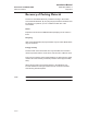
Installation Manual 308014EN, Edition 4 May 2013 Rosemount TankRadar REX Table of Contents Recovery of Products The label below is put on Rosemount Tank Gauging products as a recommendation to customers if scrapping is considered. label_180.eps Recycling or disposal should be done following instructions for correct separation of materials when breaking up the units.
Installation Manual Rosemount TankRadar REX Table of Contents TOC-8 308014EN, Edition 4 May 2013
Installation 308014EN, Edition 4 May 2013 1. Rosemount Tank Radar REX Chapter 1 Introduction Introduction The Rosemount TankRadar REX System is a monitoring and control system for tank level gauging. The system can interface various sensors, such as temperature and pressure sensors, for complete inventory control. There is a distributed intelligence in the various units of the system. The units continuously collect and process information.
Installation Manual 308014EN, Edition 4 May 2013 Rosemount Tank Radar REX Chapter 1 Introduction RS-232C Plant Host Computer TankMaster WinOpi Value Level Value Hi Lim Temp Auto Level Delay Avg Pressure Auto Auto Temp Avg Pressure 0 0 0 Enter Report Printer Alarm Log Printer Control Room Level Entry Tank1 18.000 Lo Lim 120.0 2.000 2.0 Hyst 80.0 HH Lim 20.000 LL Lim 1.000 0.0 0.200 5.0 Leak 0.5 Limit 0.
Installation 308014EN, Edition 4 May 2013 Rosemount Tank Radar REX Chapter 1 Introduction The basic parts of the Rosemount TankRadar REX System are: • The Radar Tank Gauge, RTG, is an intelligent explosion protected instrument for measuring the level of a product inside a tank. Four different Tank Connection Units can be attached in order to satisfy a variety of different applications. The RTG 3900 is equipped with auxiliary inputs such as temperature sensor inputs and analog inputs.
Installation Manual Rosemount Tank Radar REX Chapter 1 Introduction 1.1 308014EN, Edition 4 May 2013 Manual Overview This manual provides information about mechanical and electrical installation of Rosemount TankRadar REX equipment. It covers the TankRadar REX 3900 series of transmitters, and also provides instructions for TRL/2 Data Acquisition Units, Field Communication Units and Field Bus Modems. Chapter 1 provides an overview of the Rosemount TankRadar REX radar gauging system.
Installation Manual 308014EN, Edition 4 May 2013 2. Rosemount Tank Radar REX Chapter 2 Safety Safety Rosemount TankRadar REX equipment is often used in areas where flammable materials are handled and where an explosive atmosphere may be present. To protect both the plant and the personnel, precautions must be taken to ensure that this atmosphere cannot be ignited. These areas are called hazardous areas and equipment within these areas must be explosion protected.
Installation Manual Rosemount Tank Radar REX Chapter 2 Safety 2.2 308014EN, Edition 4 May 2013 Explosion Proof Explosion proof enclosures can be used when an explosion can be allowed inside the enclosure as long as it does not spread to the outside. The enclosure must be strong enough to withstand the pressure and must have narrow gaps to allow the pressure to escape without igniting the atmosphere outside of the equipment. Note! 2-2 Any substitution to non-recognized parts may impair safety.
Installation Manual 308014EN, Edition 4 May 2013 2.3 Rosemount Tank Radar REX Chapter 2 Safety European ATEX Directive Information 2.3.1 Radar Unit The REX Radar Unit has been certified to comply with Directive 94/9/EC of the European Parliament and the Council as published in the Official Journal of the European Communities No. L 100/1. Figure 2-1. Certification label ATEX for the 2015 Radar Unit (used in 3900 series radar tank gauges).
Installation Manual Rosemount Tank Radar REX Chapter 2 Safety 2.3.2 308014EN, Edition 4 May 2013 Radar Tank Gauge The 3900 Radar Tank Gauge (type TH2015-2019 Radar Unit with antenna certified for Zone 0) has been certified to comply with Directive 94/9/EC of the European Parliament and the Council as published in the Official Journal of the European Communities No. L 100/1. The 3900 series of Radar Tank Gauges is intended to be mounted directly on tank. Figure 2-2.
Installation Manual 308014EN, Edition 4 May 2013 2.3.3 Rosemount Tank Radar REX Chapter 2 Safety Transmitter Interface Card (TIC) Figure 2-3. Certification label for the Transmitter Interface Card (TIC). The Transmitter Interface Card (TIC) is mounted within the flameproof enclosure. It is required for intrinsically safe inputs such as 4-20 mA current loops and local display unit.
Installation Manual Rosemount Tank Radar REX Chapter 2 Safety 2.3.4 308014EN, Edition 4 May 2013 Temperature Multiplexer Card (TMC) Figure 2-4. Certification label for the Temperature Multiplexer Card (TMC). The Temperature Multiplexer Card (TMC) is mounted within the flameproof enclosure. It is used for connecting up to 6 temperature sensors to the REX 3900 gauge.
Installation Manual 308014EN, Edition 4 May 2013 2.3.5 Rosemount Tank Radar REX Chapter 2 Safety FF Adaptor Card (FFA) Figure 2-5. Certification label for the FF Adaptor Card (FFA). The FF Adaptor card (FFA) is mounted within the flameproof enclosure. It is, in conjunction with a Fieldbus Communication Board (BAS01ATEX1385U), used to interface to an intrinsically safe Fieldbus.
Installation Manual 308014EN, Edition 4 May 2013 Rosemount Tank Radar REX Chapter 2 Safety 2.3.6 Data Acquisition Unit (DAU) Figure 2-6. Certification label ATEX for the Data Acquisition Unit.
Installation Manual 308014EN, Edition 4 May 2013 2.3.7 Rosemount Tank Radar REX Chapter 2 Safety Remote Display Unit 40 (RDU 40) Figure 2-7. Approval label for the Remote Display Unit RDU40. The following information is provided as part of the label of the Remote Display Unit 40 (RDU 40): • Name and address of the manufacturer (Rosemount Tank Radar AB).
Installation Manual Rosemount Tank Radar REX Chapter 2 Safety 2-10 308014EN, Edition 4 May 2013
Installation Manual 308014EN, Edition 4 May 2013 Rosemount Tank Radar REX Chapter 3 Description of 3900 REX 3. Description of 3900 REX 3.1 Transmitter Head RTG 3900 REX 3900_TH.eps Depending on the type of tank connection unit that the transmitter head is mounted on, there are four types of Radar Tank Gauges. The transmitter head contains all the electronics for signal processing, communication and connection of external sensors.
Installation Manual 308014EN, Edition 4 May 2013 Rosemount Tank Radar REX Chapter 3 Description of 3900 REX 3.1.1 Transmitter Head Electronics The electronics is mounted in an exchangable unit in the explosion proof Transmitter Head. A high measurement accuracy is achieved by using digital reference circuitry, and by controlling the internal temperature by an internal heater. The 3900 transmitter head can be used on all types of TRL/2 antennas.
Installation Manual 308014EN, Edition 4 May 2013 3.1.2 Rosemount Tank Radar REX Chapter 3 Description of 3900 REX Analog Processing Card - APC The APC is used for filtering and multiplexing of analog input signals. By keeping the analog circuitry on a separate card a high Signal to Noise Ratio is achieved. 3.1.3 Transmitter Interface Card - TIC The Transmitter Interface Card (TIC) is required for intrinsically safe auxiliary inputs. The TIC includes: 3.1.
Installation Manual Rosemount Tank Radar REX Chapter 3 Description of 3900 REX 3.1.7 308014EN, Edition 4 May 2013 Metrological Seal A switch on the FCC board can be used to prevent unauthorized changes in the RTG database. The switch can be sealed in the writeinhibit position by using a special plastic cover. Internal switch TH_Top.eps Metrological Seal Figure 3-3. RTG 3900 transmitter head with metrological seal. External switch REX can also be equipped with an external metrological seal.
Installation Manual 308014EN, Edition 4 May 2013 3.2 Rosemount Tank Radar REX Chapter 3 Description of 3900 REX Antenna Types Weather Protection Hood Transmitter Head Tank Nozzle Min. 8" The Horn Antenna Gauge, RTG 3920 The Horn Antenna Gauge is designed for an 8” antenna to be used in small size openings on tanks with fixed roofs. The RTG 3920 is designed for measurement of a variety of oil products and chemicals. However, for bitumen/asphalt and similar products the Parabolic antenna is recommended.
Installation Manual 308014EN, Edition 4 May 2013 Rosemount Tank Radar REX Chapter 3 Description of 3900 REX 0.59 m Waveguide Unit 0.7 m 0.5 m Weather Protection Hood Antenna Figure 3-7. The RTG 3950 Still Pipe Gauge 0.3 m Weather Protection Hood Transmitter Head 1.0 m Housing Pressure Transducer Valve Lower Flange 6" Existing pressure vessel flange Pipe Cone 4" or Ø 100 mm Still Pipe Figure 3-8.
Installation Manual 308014EN, Edition 4 May 2013 4. Rosemount Tank Radar REX Chapter 4 The Data Acquisition Unit The Data Acquisition Unit The Data Acquisition Unit (DAU) is a complement to the Radar Tank Gauge (RTG) to interface various sensors for temperature measurement. The DAU is intrinsically safe and is connected to the RTG on the same tank. It receives its power supply from and communicates via the Transmitter Interface Card (TIC) in the RTG.
Installation Manual 308014EN, Edition 4 May 2013 Rosemount Tank Radar REX Chapter 4 The Data Acquisition Unit 4.2 Write Enable/Inhibit Switch The DAU is equipped with a switch that can be used to prevent unauthorized changes in the database (EEPROM). In order to enable programming of the EEPROM, the S1 switch must be set in the position, towards the block terminals. The switch can be locked and sealed in the write inhibit position using a wire through the clevis pins. DAU Figure 4-2.
Installation Manual 308014EN, Edition 4 May 2013 4.3 Rosemount Tank Radar REX Chapter 4 The Data Acquisition Unit Connecting the Data Acquisition Unit, DAU 2100 Instructions for connection of the Data Acquisition Unit is given on the inside of its cover. 4.3.1 Power Supply The Data Acquisition Unit receives its power via the local line from the associated Radar Tank Gauge. If the distance between the Transmitter Head and the Data Acquisition Unit is longer than 2.
Installation Manual 308014EN, Edition 4 May 2013 Rosemount Tank Radar REX Chapter 4 The Data Acquisition Unit 4.3.3 Selecting the temperature range A DAU can be configured for one of three different temperature ranges by means of a multiplexer. The multiplexer for the RTDs has two different amplification factors which are jumper selected. It is also possible to provide an offset to the measured signal by adding a current to it. X1 - OPEN X2 - OPEN DAU_TempRange.eps X3 - CLOSED Figure 4-4.
Installation Manual 308014EN, Edition 4 May 2013 5. Rosemount Tank Radar REX Chapter 5 The Remote Display Unit The Remote Display Unit RDU40 The Remote Display Unit 40 (RDU 40) is a robust display unit for outdoor use in hazardous areas. If there are less than six temperature elements per tank, the RDU 40 is the most cost-effective solution for field display. In this case the temperature elements can be connected directly to the TankRadar gauge (RTG).
Installation Manual Rosemount Tank Radar REX Chapter 5 The Remote Display Unit 5.1 308014EN, Edition 4 May 2013 Installation Unscrew and remove all six screws on the RDU40 cover. Remove the cover and take care of the locking device for the weather protection hatch. RDU40_install_master_slave.eps The RDU 40 shall be connected to the TankRadar REX junction box for cable connections. Figure 5-2.
Installation Manual 308014EN, Edition 4 May 2013 Rosemount Tank Radar REX Chapter 5 The Remote Display Unit In order to allow proper operation and to fulfil EMC requirements, the cable between the RDU 40 and the REX junction box should meet the following requirements: • Shielded cable. Minimum 3 wires. The shield shall be circular connected inside the cable gland of the RDU 40 and connected to ground in the REX junction box. • All wires must have at least 0.25 mm individual insulation.
Installation Manual Rosemount Tank Radar REX Chapter 5 The Remote Display Unit 5.2 308014EN, Edition 4 May 2013 Two RDU 40 connected to the same REX If two RDU 40 are connected to the same REX, one of them has to be configured as “slave” while the other is “master”. The slave cannot be configured or controlled individually but follows the master. Only the LCD-contrast can be individually controlled on the slave RDU 40.
Installation Manual 308014EN, Edition 4 May 2013 6. Rosemount Tank Radar REX Chapter 6 The Field Communication The Field Communication Unit The Field Communication Unit (FCU) continuously polls data from the Radar Tank Gauges and the Data Acquisition Units and stores it in a buffer memory. The Field Communication Unit is the master on the Field Bus but acts as a slave on the Group Bus. No explosion protection is provided, so the Field Communication Unit must be installed in a non-hazardous area.
Installation Manual 308014EN, Edition 4 May 2013 Rosemount Tank Radar REX Chapter 6 The Field Communication Unit 6.2 Communication Ports The Field Communication Unit has six connections for communication interface boards, X1 to X6. The connections can be individually configured as either Group Bus or Field Bus ports. There can be maximum four Group Buses or four Field Buses at the same time. Maximum configuration can be 2+4, 3+3 or 4+2 buses of each kind.
Installation Manual 308014EN, Edition 4 May 2013 6.2.2 Rosemount Tank Radar REX Chapter 6 The Field Communication RS 485 communication Each FCM interface board can be replaced with FCI interface boards for RS-485 communication. Note! 6.3 The wire terminals 1 and 3 respectively 2 and 4 on FCM board connector are parallel connected. See installation drawing. Write Inhibit/Enable Switch There is a write inhibit switch in the FCU that can be used to prevent unauthorized changes in the FCU database.
Installation Manual 308014EN, Edition 4 May 2013 Rosemount Tank Radar REX Chapter 6 The Field Communication Unit 6.4 Connecting the Field Communication Unit, FCU 2160 6.4.1 Power Supply There is a switch to select the supply voltage to either 115 V or 230 V. Check that the switch is set in the right position before power is connected. The switch is set to 230 V as standard. FCU_2160_Label.
Installation Manual 308014EN, Edition 4 May 2013 6.5 Rosemount Tank Radar REX Chapter 6 The Field Communication Redundancy In order to reduce the risk of communication failure between the TankMaster and the units connected to the TRL/2 fieldbus, two FCUs can be connected to run in parallel to provide automatic redundancy. The FCUs are connected with an extra cable allowing them to communicate. The inactive FCU constantly checks if the connected FCU is active.
Installation Manual Rosemount Tank Radar REX Chapter 6 The Field Communication Unit Local Area Network 308014EN, Edition 4 May 2013 Redundant FCU:s, FBM:s and workstations. FCU_redundant_FBM.eps With two FBM:s safe communication between the TankMaster workstation and the FCU is achieved. FCU_redundant_groupbus.eps Several Group Buses. 6-6 An FCU can connect up to four group buses. The buses can have different masters like TankMaster PC:s and DCS units.
Installation Manual 308014EN, Edition 4 May 2013 Bus Modems Emerson Process Management/Rosemount Tank Gauging supplies two types of modems (for technical details, please see chapter 14): Figure 7-1. Field Bus Modem 2180 FBM2180_USB_Top_RosemounTG.eps Field Bus Modem 2180: converts between USB or RS 232C and the TRL/2 Bus. The TRL/2 protocol is used for communication with Rosemount Tank Gauging equipment.
Installation Manual 308014EN, Edition 4 May 2013 Rosemount Tank Radar REX Chapter 7 Bus Modems 7.1 Field Bus Modem 2180 7.1.1 DIN Rail Mounting The FBM 2180 can be mounted on a DIN-rail 35 EN 50022. The following is delivered with the FBM2180 kit: • FBM 2180 TRL/2 Bus Modem • Four screws • Two DIN mounting clips 1 Attach the two DIN rail mounting clips to the back of the FBM2180 by using the four screws. There are four holes drilled on the modem housing to be used for the clips.
Installation Manual 308014EN, Edition 4 May 2013 7.1.2 Rosemount Tank Radar REX Chapter 7 Bus Modems Power Supply Use adapter 90-264 V ac/9 V dc 1.5 A for RS232 communication. FBM2180_Back.eps DO NOT use external power supply when the modem is connected to the USB port. The USB interface itself supports power to the FBM2180 modem. Power supply (polarity independent) (RS 232 communication only) Figure 7-3. 7.1.3 Power supply for RS232 TRL/2 Bus Use single twisted preferably shielded pair cable.
Installation Manual 308014EN, Edition 4 May 2013 Rosemount Tank Radar REX Chapter 7 Bus Modems 7.1.4 RS 232 Communication The serial port on the FBM2180 fits to a standard M 9P Dsub connector. Connect the modem to the COM port on the PC with a standard RS232 DTE-DCE cable (“straight” cable). FBM2180_Back / FBM2180_RS232_Top RS 232 connector RS 232 port Figure 7-5. 7.1.5 RS232 connection USB Communication For the USB port use cable type A>B. Do not use external power supply when using the USB port.
Installation Manual 308014EN, Edition 4 May 2013 7.1.6 Rosemount Tank Radar REX Chapter 7 Bus Modems USB Driver Installation The USB interface requires a Virtual COM Port driver. Rosemount TankMaster version 4.F1 and higher fully supports Virtual COM Ports. The driver is included on the Rosemount TankMaster CD version 4.F1 and higher. To install the USB driver do the following: Plug the USB cable into the FBM 2180 and to the USB port on the computer.
Installation Manual Rosemount Tank Radar REX Chapter 7 Bus Modems 308014EN, Edition 4 May 2013 Follow the instructions on the screen for the FBM 2180 Serial Port driver. 5 If you are using Windows XP operating system, you will see the warnings below appear during the USB driver installations: 6 Please click the Continue Anyway button. Our drivers are Microsoft WHQL certified and work with the operating system. 7 Once the USB drivers are installed you are ready to use the FBM 2180.
Installation Manual 308014EN, Edition 4 May 2013 7.1.7 Rosemount Tank Radar REX Chapter 7 Bus Modems Operation Front Panel The FBM 2180 front LEDs show information on power supply, communication status and communication interface. External power Gain switch Termination switch Receive RS232 Transmit USB Figure 7-7. FBM2180_Front.
Installation Manual 308014EN, Edition 4 May 2013 Rosemount Tank Radar REX Chapter 7 Bus Modems 7.1.9 USB Interface The USB interface requires a Virtual COM Port driver. Virtual COM Ports are supported by Rosemount TankMaster version 4.F1 or higher. See “USB Driver Installation” on page 5. for more information. In TankMaster™ WinSetup each FBM 2180 connected via a USB port is displayed as a virtual COM port designated FBM 2180 Serial Port.
Installation Manual 308014EN, Edition 4 May 2013 Rosemount Tank Radar REX Chapter 7 Bus Modems 7.1.11 Specifications Explosion protection None Power supply (for RS-232) DC 7-12 V, max. 50 mA Cable to Host PC RS-232: 3 m (10 ft) USB: 3 m (10 ft) Field bus over voltage protection Galvanic insulation, transient suppressors Field interface TRL/2 Computer/Host interface RS-232 or USB LED indicators External power.
Installation Manual 308014EN, Edition 4 May 2013 Rosemount Tank Radar REX Chapter 7 Bus Modems 7.2 Enraf Bus Modem, EBM An Enraf Bus Modem (EBM) is used when configuring a Rex gauge for Enraf emulation. Network Entis / TankMaster PLC EBM PC with WinSetup software for configuration of Rex CIU Enraf_Fieldbus_REX.eps Rex gauge Figure 7-10. 7-10 A system where Enraf gauges have been replaced by TankRadar Rex.
Installation Manual 308014EN, Edition 4 May 2013 7.2.1 Rosemount Tank Radar REX Chapter 7 Bus Modems Connecting the Enraf Bus Modem Modemb.eps Field bus connector PC connector Modbus/Normal (Enraf) Switch Modbus, left position Enraf, right position Baud rate Switch 2400, left position; 1200, right position most commonly used. Figure 7-11. 7.2.2 Connecting an Enraf Bus Modem (EBM).
Installation Manual Rosemount Tank Radar REX Chapter 7 Bus Modems 308014EN, Edition 4 May 2013 Below follows a short configuration description. Details are described in the Enraf Emulation Guideline (reference number 308013EN) and in TankMaster WinSetup Reference Manual (reference number 303027EN). Step 1 Connect the EBM. Step 2 Configure the gauge in WinSetup. Step 3 Install a tank in Winsetup: Required only for Hybrid / LPG systems for which the analog inputs are used.
Installation Manual 308014EN, Edition 4 May 2013 8. Rosemount Tank Radar REX Chapter 8 Junction Boxes Junction Boxes As optional equipment, a series of junction boxes can be delivered with the TankRadar Rex system. They are used to connect the various system units. FCU JB 36/42 (section 8.3) RTG with JBi (section 8.1) JB JB RTG JB EEx e (section 8.2) Alternative connections to DCS Field Bus Modem Temp. Sensor system_JB Temp. Sensor TankMaster PC workstations in network DAU Figure 8-1. 8.
Installation Manual 308014EN, Edition 4 May 2013 Rosemount Tank Radar REX Chapter 8 Junction Boxes 8.1.2 Design 8.1.3 • The box is sealed according to IP65. • Temperature range is -40°C to +70°C (-40°F to +158°F). Cable Inlets - RTG 3900 On the left-hand side (X12) there are two 1/2 in. and one 3/4 in. inlets. There are 15 terminals for intrinsically safe cables to analog inputs, DAU or Display Panel and up to 6 temperature sensors. On the right-hand side (X11) there are two 3/4 in. and one 1/2 in.
Installation Manual 308014EN, Edition 4 May 2013 Junction Boxes for Intrinsically Safe and EEX e environments JB_general_ed3 8.2 Rosemount Tank Radar REX Chapter 8 Junction Boxes JB 140-15 (EEX i) JB 140-11 (EEX e) DAU / RDU Cable ~ 2 m cable with protective hose Figure 8-3. 8.2.1 ~ 2 m cable with protective hose 5 x M25 TRL/2 Bus, Analog outputs, Relay output, Power 230/ 115 VAC Intrinsically Safe and Explosion Proof Junction Boxes.
Installation Manual 308014EN, Edition 4 May 2013 Rosemount Tank Radar REX Chapter 8 Junction Boxes 8.2.3 Junction Boxes with Conduit Outlets GUA-L US_jb_2 EXP-FLEX Transmitter head with 3/4 inch female output Figure 8-4. GUA-T Rigid conduit pipes Connection to rigid pipes via a junction box with conduit outlets. In the US wires from the transmitter head must be enclosed in a protective steel braided hose.
Installation Manual 308014EN, Edition 4 May 2013 Connection of Temperature Sensors 8.3.1 Junction Box JBT The JBT has two openings for M25 glands suitable for 9-16 mm cables. Temperature sensors are attached directly to the JBT as illustrated in Fig. 8-5 and Fig. 8-6. Up to six temperature sensors can be connected via the JBT to the REX gauge or to a Data Acquisition Unit (DAU). Level 6.
Installation Manual 308014EN, Edition 4 May 2013 Rosemount Tank Radar REX Chapter 8 Junction Boxes 8.3.2 Junction Box JB 36/42 JB36 and JB42 are used for intrinsically safe connection of up to 14 temperature sensors to a Data Acquisition Unit (DAU). 12 sensors for JB 36 if 3-wire connection is used. JB 36 and JB42 have three openings for M25 glands, suitable for 9-16 mm cable diameter. Temperature sensors are connected to the JB 36/42 Junction Box and the DAU via cable as illustrated in Fig. 8-7.
Installation Manual 308014EN, Edition 4 May 2013 9. Rosemount Tank Radar REX Chapter 9 Connection to Computer Networks Connection to Computer Networks A host computer can be connected either to a PC with TankMaster Software or directly to the Field Communication Units (FCUs). The Rosemount TankRadar REX system can be connected to all major DCS systems, such as Foxboro, Honeywell, Rosemount and Yokogawa. New interfaces can be developed on request.
Installation Manual Rosemount Tank Radar REX Chapter 9 Connection to Computer Networks 9-2 308014EN, Edition 4 May 2013
Installation Manual 308014EN, Edition 4 May 2013 Rosemount Tank Radar REX Chapter 10 Mechanical Installation 10. Mechanical Installation To achieve precise and trouble free measurement, it is very important to mount the Radar Tank Gauge correctly on the tank. Please note that if an ullage plug is required, it has to be installed separately as there is no ullage plug on the Horn Antenna Gauge or the Parabolic Antenna Gauge. Note! 10.1 Please see the installation drawings for more information.
Installation Manual 308014EN, Edition 4 May 2013 Rosemount Tank Radar REX Chapter 10 Mechanical Installation 10.1.2 Free Space Requirements There are two flanges available for the Horn Antenna Gauge. One inclines the gauge 4° and the other is horizontal. See installation drawing for flange dimensions. The radar beam is over 30° wide.
Installation Manual 308014EN, Edition 4 May 2013 Rosemount Tank Radar REX Chapter 10 Mechanical Installation 10.1.3 Dimensions 350 mm 3920_Dimensions.eps 400 mm 350 mm 177 mm Figure 10-3. RTG 3920 dimensions.
Installation Manual 308014EN, Edition 4 May 2013 Rosemount Tank Radar REX Chapter 10 Mechanical Installation 10.1.4 Installation on the tank Follow this Step by Step instruction when installing the Cone Antenna Gauge. Note! When determining the dimensions for conduits (if used), note that the Horn Antenna Gauge may be inclined 4° towards the center of the tank. See Figure 10-2. Use flexible conduits close to the Radar Tank Gauge.
Installation Manual 308014EN, Edition 4 May 2013 Rosemount Tank Radar REX Chapter 10 Mechanical Installation 4 Put the Transmitter Head onto the flange. Fit and tighten the four M10 screws with washers. 5 The Weather Protection Hood is tightened with a single screw at the top of the transmitter head. Transmitter head Cone_pict3.eps Four M10 screws and washers RTG3900_WeaProtMount.
Installation Manual Rosemount Tank Radar REX Chapter 10 Mechanical Installation 10.2 308014EN, Edition 4 May 2013 Mounting the Parabolic Antenna Gauge See also Mechancial Installation drawings 9150072-982, 9240003-944, 947 for further information. 10.2.1 Inclination The inclination of the gauge should not exceed 1.5 ° towards the center of the tank. For products with high condensation, like bitumen/asphalt applications, the radar beam should be directed vertically without any inclination.
Installation Manual Rosemount Tank Radar REX Chapter 10 Mechanical Installation 3930_FlangeReq_2.eps 308014EN, Edition 4 May 2013 Maximum inclination of flange towards the tank center. Figure 10-6. Maximum inclination of flange towards the tank wall. 3930_FlangeReq_3.eps Figure 10-5.
Installation Manual Rosemount Tank Radar REX Chapter 10 Mechanical Installation 308014EN, Edition 4 May 2013 Inclination - Flange Ball model T38-W Flange Ball T38-W can be welded at a maximum angle of 20° between the flange and the Flange Ball surface. Inclination_T38W.eps 60 mm Figure 10-7. 10-8 Maximum inclination with Flange Ball T38W.
Installation Manual 308014EN, Edition 4 May 2013 Rosemount Tank Radar REX Chapter 10 Mechanical Installation 10.2.2 Free Space Requirements The radar beam of the Parabolic Antenna Gauge is 10° wide. Obstacles (construction bars, pipes larger than Ø 2", etc.) within the radar beam are generally not accepted, as these can result in disturbing echoes. However, in most cases, a smooth tank wall or heating coils will not have any significant influence on the radar beam.
Installation Manual 308014EN, Edition 4 May 2013 Rosemount Tank Radar REX Chapter 10 Mechanical Installation 10.2.3 Socket Requirements When using a Ø 20" socket the height of the socket must not exceed 0.5 m. Sockets with larger diameter may be higher. In this case there must be a free passage for the radar beam within a 5° angle from the edge of the Parabolic Reflector to the bottom end of the socket. Ø > 500 mm (20 inch) Socket height maximum 0.5 Mimimum 1.
Installation Manual 308014EN, Edition 4 May 2013 Rosemount Tank Radar REX Chapter 10 Mechanical Installation 10.2.5 Mounting the Flange Ball model T30 1 Use a flange which is 6 - 30 mm thick. Make sure that the diameter of the hole is 96 mm. Make a small recess at one side of the flange hole. 2 Put the O-ring on the flange and insert the Flange Ball into the flange hole. Make sure that the pin on the side of the Flange Ball fits into the corresponding recess on the flange.
Installation Manual 308014EN, Edition 4 May 2013 Rosemount Tank Radar REX Chapter 10 Mechanical Installation 10.2.6 Mounting the Flange Ball model T38-W The Flange Ball T38 is welded to the flange. To mount the T38 do the following: Make sure that the diameter of the hole is 116 ± 2 mm. 2 Let the protection plates remain on the Flange Ball until the welding is finished. These plates protect the surface of the Flange Ball from welding sparks.
Installation Manual 308014EN, Edition 4 May 2013 Rosemount Tank Radar REX Chapter 10 Mechanical Installation 4 If the tank flange is inclined, make sure that the Flange Ball is welded in such a way that the Flange Ball is horizontal when it is mounted on the tank. The tank flange inclination should be less than 20 degrees. 5 Remove the protection plates when the Flange Ball is welded to the flange. Inclination_T38W.eps 60 mm Protection plate 11.4.
Installation Manual 308014EN, Edition 4 May 2013 Rosemount Tank Radar REX Chapter 10 Mechanical Installation 10.2.7 Mounting the Antenna M5x5 1 Fit the Parabolic Reflector onto the Antenna Feeder and mount the five M5 screws. 2 Tighten the screws. 3 Put the two O-rings in the grooves on the upper surface of the Flange Ball. Parabolic reflector 12.2.eps 12.1.eps Antenna feeder 2 O-rings Flange Ball Grooves 12.3.
Installation Manual 308014EN, Edition 4 May 2013 Rosemount Tank Radar REX Chapter 10 Mechanical Installation Nut 4 Turn the flange around and insert the antenna feeder into the flange hole. Mount the washers and nuts. 5 Tighten the finger nut and the upper nut loosely. 6 Place the antenna and flange assembly on the tank nozzle and tighten the flange screws. Tab Washer Finger Nut Flange Washer Ball Stop Washer 12.4.eps Antenna Feeder Upper Nut 12.6.eps 12.5.
Installation Manual 308014EN, Edition 4 May 2013 Rosemount Tank Radar REX Chapter 10 Mechanical Installation 7 Place the TRL/2 adapter on top of the antenna feeder. 8 Place the level on top of the TRL/2 adapter and adjust the antenna to an inclination of 1.5° towards the center of the tank. 12.7.eps TRL/2 Adapter 3 1 0 , 1, 0, 0, 1, , 0 1 3 Note! Make sure the air bubble touches, but doesn´t overlap the 1.5° mark. Guide pins Tank center Incline 1.
Installation Manual 308014EN, Edition 4 May 2013 Rosemount Tank Radar REX Chapter 10 Mechanical Installation Direct towards tank center Guide pin 9 Rotate the antenna so the guide pins on the TRL/2 adapter are directed towards the center of the tank. Tighten the finger nut. 12.13.eps Guide pin Tank Tank center TH_direction.eps Antenna Guide pins x2 12.1.eps Stop screws Wave Guide Unit 10 Mount the Waveguide Unit into the base of the Transmitter Head.
Installation Manual 308014EN, Edition 4 May 2013 Rosemount Tank Radar REX Chapter 10 Mechanical Installation 11 Carefully mount the Transmitter Head onto the TRL/2 adapter. Make sure that the guide pins on the TRL/2 adapter fits into the holes on the base of the transmitter head. Tighten the 4 screws. x4 Guide pin 12.10.eps Guide pin 3 1 0 , 1, 0, 0, 1, 0 1 3 12.11.
Installation Manual 308014EN, Edition 4 May 2013 Rosemount Tank Radar REX Chapter 10 Mechanical Installation RTG3900_WeatherProtection.eps 13 Replace the Weather Protection Hood onto the Transmitter Head. 12.12.eps 14 Tighten the finger nut firmly. Tighten the upper nut and secure by folding the tab washer over the nut.
Installation Manual Rosemount Tank Radar REX Chapter 10 Mechanical Installation 10.3 308014EN, Edition 4 May 2013 Mounting a Still Pipe Gauge 10.3.1 Introduction This instruction covers installation of the RTG 3950 Still-pipe array antenna. It is available for pipe size 5, 6, 8, 10 and12 inch. The RTG 3950 Still-pipe Array antenna is designed for still-pipe mounting and can be mounted on existing still-pipes without taking the tank out of operation.
Installation Manual 308014EN, Edition 4 May 2013 Rosemount Tank Radar REX Chapter 10 Mechanical Installation 10.3.2 Still Pipe Requirements The RTG 3950 Still-pipe Array antenna fits 5", 6", 8", 10" and 12" flanges and pipes. The adaption is accomplished by selecting a suitable Stillpipe Array antenna. The gauge has a meeting flange for sealing of the tank. The still pipe must be vertical within 0.5° (0.2 m over 20 m).
Installation Manual 308014EN, Edition 4 May 2013 Rosemount Tank Radar REX Chapter 10 Mechanical Installation 10.3.4 Recommended Installation When constructing new tanks, an 8" still pipe or larger is recommended. This is especially relevant in tanks with sticky, viscous products. Before manufacturing a new still pipe, we recommend that you contact Emerson Process Management / Rosemount Tank Gauging for advice.
Installation Manual 308014EN, Edition 4 May 2013 Rosemount Tank Radar REX Chapter 10 Mechanical Installation 10.3.5 Free space requirements - RTG 3950 Fixed Version The gauge requires the following free space for mounting on a Still-pipe: 3950_Flange_FreeSpace.eps Min. 500 mm 700 mm 620 mm Figure 10-11. Free space requirements for flange mounted REX 3950.
Installation Manual 308014EN, Edition 4 May 2013 Rosemount Tank Radar REX Chapter 10 Mechanical Installation 10.3.6 Installation of the 3950 Fixed Version on the tank Follow this instruction when mounting the RTG 3950 Still-pipe Array antenna. 3950_Flange_Step1.eps Note! If there is no flange on the still pipe a clamp flange must be mounted. 1 Insert the antenna feeder into the flange hole. 2 Tighten the nut. Antenna feeder 3950_Flange_Step2.
Installation Manual 308014EN, Edition 4 May 2013 Rosemount Tank Radar REX Chapter 10 Mechanical Installation Put the antenna and flange assembly on the tank nozzle and tighten the flange screws. 4 Put the TRL/2 adapter on top of the antenna feeder. Note that there is a guide pin inside the TRL/2 adapter that fits the groove on the outside of the antenna feeder. Tighten the nut firmly. 5 Mount the Waveguide Unit into the base of the Transmitter Head.
Installation Manual 308014EN, Edition 4 May 2013 Rosemount Tank Radar REX Chapter 10 Mechanical Installation 6 Carefully mount the Transmitter Head onto the TRL/2 adapter. Make sure that the guide pins on the TRL/2 adapter fits into the holes on the base of the transmitter head. Guide pins (x 2) TRL/2 adapter 3950_Flange_Step6.eps Tighten the 4 screws and nuts. 3950_Flange_Step7.eps 7 10-26 Replace the Weather Protection Hood on the Transmitter Head.
Installation Manual 308014EN, Edition 4 May 2013 Rosemount Tank Radar REX Chapter 10 Mechanical Installation Connect the electrical cabling and configure the gauge by using the TankMaster WinSetup software (see TankMaster WinSetup Reference Manual). 3950_Flange_Step8.
Installation Manual 308014EN, Edition 4 May 2013 Rosemount Tank Radar REX Chapter 10 Mechanical Installation 10.3.7 Free space requirements - RTG 3950 Inclined Version The gauge requires the following free space for mounting on a tank nozzle: Min. 500 mm 3950_FreeSpace_inclined.eps 510 mm 590 mm Figure 10-12. Free space requirements for REX 3950 with quick opening hatch.
Installation Manual 308014EN, Edition 4 May 2013 Rosemount Tank Radar REX Chapter 10 Mechanical Installation 3950_FreeSpace_inclined_open.eps A Pipe Size A (mm) 5” 430 6” 448 8” 480 10” 518 12” 545 Figure 10-13. Make sure that there is sufficient space to open the cover.
Installation Manual 308014EN, Edition 4 May 2013 Rosemount Tank Radar REX Chapter 10 Mechanical Installation 10.3.8 Installation of the RTG 3950 Inclined Version 3950_3_cover_mount_gasket.eps Follow this instruction when mounting the Inclined version of the RTG 3950 Still-pipe Array antenna on a Still-pipe. 1 Mount the cover on the nozzle and tighten the flange screws. Leave two holes free for mounting of the Stand Bracket.
Installation Manual 308014EN, Edition 4 May 2013 Rosemount Tank Radar REX Chapter 10 Mechanical Installation 3 Mount the antenna on the lid. 4 Tighten the nut. 3950_3_antenna_mount.eps Antenna 3950_3_antenna_tighten.
Installation Manual 308014EN, Edition 4 May 2013 Rosemount Tank Radar REX Chapter 10 Mechanical Installation 5 Make sure that the O-ring is properly seated all around the cover and that it is pressed down at the Hand Dip Plate. Locking screw 6 Close the lid and tighten the locking screw. Two screws 7 Place the Stand Bracket on the desired side of the flange. Attach the Stand bracket with the two small screws.
Installation Manual 308014EN, Edition 4 May 2013 8 Insert the flange screws. Tighten so the Stand Bracket is firmly fixed. Check that all flange screws are firmly tightened. 9 Mount the Stand on the Stand Bracket. Attach the screws loosely so the Stand can be slightly tilted (this makes it easier to mount the Waveguide Connection, see step 12). 3950_3_bracket2.eps Flange Screws Rosemount Tank Radar REX Chapter 10 Mechanical Installation Stand 3950_3_stand.
Installation Manual 308014EN, Edition 4 May 2013 Rosemount Tank Radar REX Chapter 10 Mechanical Installation 10 Mount the Transmitter Head on the Stand. Check that the guide pins on the stand fits to the corresponding holes on the Transmitter Head. Tighten the nuts so the Transmitter Head is firmly attached to the Stand. Nuts x 4 3950_3_TH_mount.eps Guide pins x 2 11 Put the Waveguide Unit into the base of the Transmitter Head. It can only be entered one way. (Do not mount the two M6 stop screws yet!).
Installation Manual 308014EN, Edition 4 May 2013 Rosemount Tank Radar REX Chapter 10 Mechanical Installation 12 Mount the Waveguide Connection. 3950_3_waveguide_mount.eps Waveguide Connection 13 Tighten the lower nut by hand until the antenna is completely inserted into the Waveguide Connection. Tighten the nut loosely so the Waveguide Connection can be slightly rotated. 3950_3_waveguide_mount_nut.
Installation Manual 3950_3_Stand_Tighten.eps 3950_3_waveguide_connection.eps Rosemount Tank Radar REX Chapter 10 Mechanical Installation 308014EN, Edition 4 May 2013 15 Tighten the lower nut on the Waveguide Connection firmly. Nut 16 Lift the transmitter head slightly until the Waveguide Unit inside the base of the Transmitter head is fully inserted. Tighten the four screws on the side of the stand so it is firmly attached to the bracket.
Installation Manual 308014EN, Edition 4 May 2013 Rosemount Tank Radar REX Chapter 10 Mechanical Installation 3950_3_WeatherProtection.eps 18 Mount the Weather Protection Hood and tighten the screws. The horizontal hood has one screw on each side of the gauge. 19 Loosen the Sleeve Nut and check that the cover can be easily opened and closed. Close the cover and tighten the Sleeve Nut again. Check that the Waveguide Connection can be properly attached to the transmitter head. Sleeve Nut 3950_3_Open_test.
Installation Manual Rosemount Tank Radar REX Chapter 10 Mechanical Installation 10.4 308014EN, Edition 4 May 2013 Mounting a LPG/LNG Gauge The LPG/LNG Gauge fits to a 6" flange and requires a still pipe for measurement. Please refer to the mechanical installation drawing for more detailed information of the requirements on the installation of the LPG/LNG Gauge. 10.4.1 Temperature and Pressure Measurement.
Installation Manual 308014EN, Edition 4 May 2013 Rosemount Tank Radar REX Chapter 10 Mechanical Installation Marking The Reference Pin is directed towards the bolt hole on the pipe flange. StillPipe_RefPin.eps Still Pipe Flange seen from above Bolt hole Align Reference Pin and bolt hole within 1° StillPipe_Alignment.eps Maximum 1° Maximum 0.5° Figure 10-14. Still Pipe requirements.
Installation Manual 308014EN, Edition 4 May 2013 Rosemount Tank Radar REX Chapter 10 Mechanical Installation 10.4.3 Reference Pin and Reflector One of the holes on the Still Pipe is used for mounting a Reference Pin which enables verification of the measurement when the tank is pressurized. The Reflector is mounted at the lower end of the Still Pipe and is integrated with a ring that is used for calibrating the gauge.
Installation Manual 308014EN, Edition 4 May 2013 Rosemount Tank Radar REX Chapter 10 Mechanical Installation Reflector_SCH40.eps Ring is marked 4” SCH40 Figure 10-16. Mounting of reflector on pipe 4 inch SCH 40. Reflector_DN100.eps Ring is marked DN100 Figure 10-17. Mounting of reflector on pipe DN 100.
Installation Manual Rosemount Tank Radar REX Chapter 10 Mechanical Installation 308014EN, Edition 4 May 2013 10.4.4 Extension Pipe for Minimum Distance. The Radar Tank Gauge should be placed so that there is always 800 mm or more between the flange and the maximum product level. If the tank is filled completely, an extension pipe can be mounted to raise the Radar Tank Gauge so that it measures correctly all the way up to the maximum level. See Figure 10-18. LPGREX_Extension.
Installation Manual 308014EN, Edition 4 May 2013 Rosemount Tank Radar REX Chapter 10 Mechanical Installation 10.4.5 Installation on the tank. Follow this step by step instruction when installing the LPG/LNG Gauge. Note! There must be a clear mark on the pipe flange to show the direction of the reference pins in the still pipe. Carefully check that the Closing is mounted in the appropriate angle relative to that mark. See also the installation drawings. See chapter 13 for list of drawings.
Installation Manual 308014EN, Edition 4 May 2013 Rosemount Tank Radar REX Chapter 10 Mechanical Installation 5 Place customer supplied gasket on the Mounting Flange. Carefully fit the Pipe Cone into the still pipe and tighten the Closing onto the Mounting Flange (customer supplied screws and nuts). Direct the Closing so that the marking hole aligns with the notch or mark on the pipe flange. 6 The tank is now sealed and can, as far as Rosemount Tank Gauging equipment is concerned, be pressurized.
Installation Manual 308014EN, Edition 4 May 2013 Rosemount Tank Radar REX Chapter 10 Mechanical Installation 9 4 M10 screws and washers Guide pins Remove the yellow protection cap but do not remove the rubber cone. Fit the Transmitter Head and the Housing onto the flange. Carefully check that the Guide Pins enter their respective holes. Tighten using four M10 screws and washers. Protection cap 3960_Housing_Mount.eps Do not remove this cone! Flange Screw RTG3900_WeaProtMount.
Installation Manual Rosemount Tank Radar REX Chapter 10 Mechanical Installation 10-46 308014EN, Edition 4 May 2013
Installation Manual 308014EN, Edition 4 May 2013 Rosemount Tank Radar REX Chapter 11 Electrical Installation of the 11. Electrical Installation of the REX Gauges Warning! Isolate and terminate ends of unused wires. The intrinsic safety may be jeopardized if any cable ends are hanging loose. Use certified battery operated instruments only. Use Rosemount Tank Gauging original spare parts only. Note! See the instructions in the electrical installation drawings for further information.
Installation Manual 308014EN, Edition 4 May 2013 Rosemount Tank Radar REX Chapter 11 Electrical Installation of the 115 VAC Cable Length 60 VAC 0.75 mm2 (AWG 18 or similar) 1.5 mm2 (AWG 16 or similar) 0.75 mm2 (AWG 18 or similar) 1.5 mm2 (AWG 16 or similar) 2.5 mm2 (AWG 14 or similar) 10 V 4 2 100 m 328 ft. 4 2 200 m 656 ft. 9 4 8 5 400 m 1312 ft. 8 22 10 600 m 1969 ft. 12 Table 11-1. 18 Voltage drop at different cable lenghts for 115 VAC and 60 VAC systems.
Installation Manual 308014EN, Edition 4 May 2013 11.2 Rosemount Tank Radar REX Chapter 11 Electrical Installation of the Cabling for TRL/2 Bus The TRL/2 Bus requires a twisted and shielded pair with an area of min 0.50 mm2 (AWG 20 or similar). The maximum length of the TRL/2 Bus is approximately 4 km. The TRL/2 Bus can normally use existing cables in the tank area.
Installation Manual 308014EN, Edition 4 May 2013 Rosemount Tank Radar REX Chapter 11 Electrical Installation of the 11.5 Connecting the Radar Tank Gauge 3900 The RTG 3900 is equipped with two cable outputs for intrinsically safe and non-intrinsically safe connections. Wires are clearly marked with numbers and designation of wires is shown on a printed plate at the cable outputs. The transmitter can also be equipped with an integrated junction box (JBi). TH3900_Twoversions.
Installation Manual 308014EN, Edition 4 May 2013 Rosemount Tank Radar REX Chapter 11 Electrical Installation of the The RTG 3900 version without Integrated Junction Box is delivered with a 2 m long cable. If the distance between the transmitter and connected devices is longer than 2 meters, a junction box must be used to connect an extension cable. The extension cable must not be longer than 50 m.
Installation Manual 308014EN, Edition 4 May 2013 Rosemount Tank Radar REX Chapter 11 Electrical Installation of the 11.5.1 Cable Outputs The transmitter has two cable outputs W11 and W12. Both outputs have 3/4 inch female NPT cable entries. The W12 cable outputs has different wiring depending on the installed option. The wires are clearly marked with numbers and the designation of the wires is shown on a printed plate at the cable output.
Installation Manual 308014EN, Edition 4 May 2013 Rosemount Tank Radar REX Chapter 11 Electrical Installation of the 11.5.2 Wiring Wires are clearly marked with numbers and designation of wires is shown on a printed plate at the cable outputs. The integrated Junction Box has sockets for intrinsic (X12) and non-intrinsic (X11) connections. The numbering shown in the following description is applicable to both versions. X12 EEx i Figure 11-4. TH3900_X11_X12.
Installation Manual 308014EN, Edition 4 May 2013 Rosemount Tank Radar REX Chapter 11 Electrical Installation of the Non-Intrinsically safe side - EEx e Terminal X11 is used for the following connections in the basic version: Connection Description 1 Power supply L, L1+ 2 Power supply N, L2- 3 TRL/2 Bus 4 TRL/2 Bus 5 Relay K1A 6 Relay K1B 7 Relay K2A (optional) 8 Relay K2B (optional) Table 11-6. Connections to terminal X11. It is recommended that shielded cable is used.
Installation Manual 308014EN, Edition 4 May 2013 Rosemount Tank Radar REX Chapter 11 Electrical Installation of the 11.5.3 Options The REX gauge can be equipped with an Analog Output in active or passive mode. There are also several communication protocols that can be emulated.
Installation Manual 308014EN, Edition 4 May 2013 Rosemount Tank Radar REX Chapter 11 Electrical Installation of the Enraf Bus Connection Description 1 Power supply L, L1+ 2 Power supply N, L2- 3 Enraf bus 4 Enraf bus 5 Relay K1A 6 Relay K1B 7 Relay K2A (optional) 8 Relay K2B (optional) Tankway L&J Connection 11-10 Description 1 Power supply L, L1+ 2 Power supply N, L2- 3 Bus power (red) 4 Signal ground (white) 5 Relay K1A 6 Relay K1B 7 Computer (black) 8 Encoder (green)
Installation Manual 308014EN, Edition 4 May 2013 Rosemount Tank Radar REX Chapter 11 Electrical Installation of the Varec mark/space Description Connection Description (Powered by Varec busa) 1 Power supply L, L1+ Bus power 2 Power supply N, L2- Signal ground 3 Bus power Bus power 4 Signal ground Signal ground 5 Relay K1A Relay K1A 6 Relay K1B Relay K1B 7 Mark Mark 8 Space Space a. See VAREC Emulation Guideline, Ref. no. 308015 E, for detailed information.
Installation Manual 308014EN, Edition 4 May 2013 Rosemount Tank Radar REX Chapter 11 Electrical Installation of the Tiway Connection Description 1 Power supply L, L1+ 2 Power supply N, L2- 3 TRL/2 Bus 4 TRL/2 Bus 5 Relay K1A 6 Relay K1B 7 Tiway bus (+) 8 Tiway bus (-) Termination of last transmitter on Tiway bus: Connection Description 6 Shield 7 Tiway bus (+) 8 Tiway bus (-) Foundation™ Fieldbus See the TankRadar REX Tank Gauging System with Foundation Fieldbus reference manual
Installation Manual 308014EN, Edition 4 May 2013 Rosemount Tank Radar REX Chapter 11 Electrical Installation of the 11.5.4 Power The 3900 REX transmitter accepts 100-240 VAC mains voltage. As an option TankRadar REX can be adapted to 37-70 VAC, 48-99 VDC or 24 VDC. The built-in Transformer Rectifier Card (TRC) automatically adapts to the connected supply voltage. See Chapter 14: Technical Data for further details. Terminals 1 to 4 have double connections to allow daisy-chain connections.
Installation Manual 308014EN, Edition 4 May 2013 Rosemount Tank Radar REX Chapter 11 Electrical Installation of the 11.5.5 TRL/2 Bus The transmitter is connected to a workstation via a a Field Communication Unit (FCU) and a Field Bus Modem (FBM). The FBM converts the USB (or RS232) signal to a TRL/2 Modbus signal. Each TRL/2 Bus can connect up to 8 units. FCU TRL/2 Bus FBM X11_TRL2Bus .eps TRL/2 Bus Figure 11-6.
Installation Manual 308014EN, Edition 4 May 2013 Rosemount Tank Radar REX Chapter 11 Electrical Installation of the 11.5.6 Relays You can use two relay ports if the optional Relay Output Card (ROC) is installed. Different transmitter variables can be chosen to trigger the relay to change state. See TankMaste WinSetup Reference Manual for further information on how to configure relays connected to a REX transmitter. K1A K1B X11_Relay.eps K2A K2B Figure 11-7. Connecting to the relay ports.
Installation Manual 308014EN, Edition 4 May 2013 Rosemount Tank Radar REX Chapter 11 Electrical Installation of the Normally Open/Closed refers to the contact position when a relay is deenergized. This is also referred to as the Alarm state. The terminology can be summarized as follows: Normally Closed Closed Open Normally Open Open Closed Deenergized Energized Deenergized Energized Not active Active Not active Active Alarm (Reset) Normal Alarm (Reset) Normal Table 11-7.
Installation Manual 308014EN, Edition 4 May 2013 Rosemount Tank Radar REX Chapter 11 Electrical Installation of the 11.5.7 Analog Output The REX transmitter can be equipped with one 4-20 mA analog output. The output can be set to either Passive or Active mode. The output mode is controlled by jumper settings on the FCC card (see REX Service Manual for more information). The Analog Output replaces the second relay and is connected as illustrated below.
Installation Manual 308014EN, Edition 4 May 2013 Rosemount Tank Radar REX Chapter 11 Electrical Installation of the 11.5.8 Temperature Sensors Up to six spot temperature elements can be connected to the REX transmitter if the Temperature Multiplexer Card (TMC) is installed. The TMC board must be configured in accordance with the type of sensor that is used (see chapter 4.1.
Installation Manual 308014EN, Edition 4 May 2013 X12_SpotTemp.eps Rosemount Tank Radar REX Chapter 11 Electrical Installation of the Figure 11-10. Connecting three-wire independent temperature sensors to the X12 terminal. Average/Multiple Spot elements Average and multiple spot elements use one wire per sensor and one common low-end connection as well as one common return current.
Installation Manual Rosemount Tank Radar REX Chapter 11 Electrical Installation of the 308014EN, Edition 4 May 2013 11.5.9 Analog Inputs X12_AnalogInput.eps REX supports two high precision analog inputs. Using the analog inputs requires the Transmitter Interface Card (TIC). Analog Input 1 may be used to connect up to 3 HART Slaves, see Chapter 11.5.10: HART Slaves. Figure 11-12. Connection of analog input instruments. Use the TankMaster WinSetup program to configure Range Values and Alarm Levels.
Installation Manual 308014EN, Edition 4 May 2013 Rosemount Tank Radar REX Chapter 11 Electrical Installation of the 11.5.10 HART Slaves X12_HARTSlave.eps HART slaves are connected to Analog Input 1. Connection to HART devices requires a Field Communication Card (FCC) equipped with optional HART modem. Figure 11-13. Connection of HART slaves. A maximum of 3 HART slaves can be connected to the REX gauge in multi-drop configuration.
Installation Manual 308014EN, Edition 4 May 2013 Rosemount Tank Radar REX Chapter 11 Electrical Installation of the 11.5.11 DAU/RDU 40 X12_RDU40_SDAU.eps REX can interface a standard DAU or the stand-alone Remote Display Unit (RDU 40). The display panel uses three wires: • Display panel supply voltage • Signal • Ground DS GND DS + DS Figure 11-14. Connecting a Remote Display Unit (RDU 40) or a DAU.
Installation Manual 308014EN, Edition 4 May 2013 Rosemount Tank Radar REX Chapter 12 Sensor Installation 12. Sensor Installation The TankRadar REX system includes various integrated equipment such as temperature sensors and Water Level Sensors. 12.1 Temperature Sensors Up to six temperature sensors can be connected to a REX Radar Transmitter Gauge (RTG). By using a Data Acquisition Unit (DAU) a maximum of 14 temperature sensors can be used in a tank.
Installation Manual 308014EN, Edition 4 May 2013 Rosemount Tank Radar REX Chapter 12 Sensor Installation On fixed roof tanks the MST is attached to a flange mounted on a suitable nozzle. M25 or ½ in. BSP Maximum level 0.5 - 1 m Uppermost spot element 7-12 kg (15-26 lbs) 320 mm MultipleSpot.eps First spot element 0.5 - 1 m 0.5 - 1 m Figure 12-2. Installation of Multiple Spot Temperature sensors. On floating roof tanks the MST can be mounted in a Still Pipe as illustrated in Fig. 12-3. M25 or ½ in.
Installation Manual 308014EN, Edition 4 May 2013 Rosemount Tank Radar REX Chapter 12 Sensor Installation For Custody Transfer applications, API chapter 7 recommends a minimum of one temperature sensor per 3 meters (10 feet) as shown in Figure 12-4. Emerson Process Management/Rosemount Tank Gauging may in some cases recommend a higher number of temperature sensors for tanks used for Custody Transfer, depending on how the tanks are operated. TempSpot_Position.eps 0.5 - 1 m Minimum level 0.
Installation Manual 308014EN, Edition 4 May 2013 Rosemount Tank Radar REX Chapter 12 Sensor Installation TempSensConfig.eps 12-5. The configuration distance in TankMaster refers to the distance above Zero Level T2-D T2 T1-D D Figure 12-5. Zero Level T1 T1, T2 etc. are sensor positions according to Required System Information (RSI) Form Configuration distance is measured from Zero Level.
Installation Manual 308014EN, Edition 4 May 2013 Water Level Sensor The Water Level Sensor (WLS) measures the free water level below an oil surface. It outputs a 4-20 mA signal which is connected to the level gauge. The WLS can also be equipped with integrated Multiple Spot Temperature sensors. Up to six temperature sensors can be connected to a Rosemount TankRadar REX transmitter. 12.2.
Installation Manual 308014EN, Edition 4 May 2013 Rosemount Tank Radar REX Chapter 12 Sensor Installation 12.2.2 Configuration It is important that the 4 mA and the 20 mA levels are properly configured in order to obtain correct water level readings from the WLS. The distance “X” between the Tank Zero Level and the Water Zero Level has to be considered when configuring the WLS. “X” can be calculated from known tank distances as illustrated in Fig. 12-8. Tank Reference point Mark wls_geometry_version2.
Installation Manual 308014EN, Edition 4 May 2013 Rosemount Tank Radar REX Chapter 12 Sensor Installation For inventory management with TankMaster WinOpi the WLS is configured in TankMaster WinSetup. The Lower Range Value (4 mA) and the Upper Range Value (20 mA) are given by the following formulas: Upper Range Value (20 mA) = LA + X Lower Range Value (4 mA) = X where LA is the active length of the Water Level Sensor, and X is the distance between the Water Zero Level and the Tank Zero Level.
Installation Manual 308014EN, Edition 4 May 2013 Rosemount Tank Radar REX Chapter 12 Sensor Installation The Water Zero Level is above the Tank Zero Level. In this case the 4 mA point on the WLS is above the Tank Zero Level. Note that when the 4 mA point is above the tank Zero Level the 4 mA value is positive, i.e. X>0. wls_open_above_v2.eps 20 mA X>0 Water Zero Level Tank Zero Level 4 mA 12-8 Example: LA=500 mm, X=70 mm. 4 mA value=70 mm. 20 mA value=500 + 70=570 mm.
Installation Manual 308014EN, Edition 3/Rev. C May 2013 Rosemount Tank Radar REX Chapter 13 List of Drawings 13. List of Drawings 13.
Installation Manual Rosemount Tank Radar REX Chapter 13 List of Drawings 13.2 13.3 13-2 308014EN, Edition 3/Rev.
Installation Manual 308014EN, Edition 3/Rev. C May 2013 13.4 13.
Installation Manual Rosemount Tank Radar REX Chapter 13 List of Drawings 13.7 13.8 308014EN, Edition 3/Rev. C May 2013 Junction Boxes - JB Junction Box JB 140-11 EExe 9150 072-053 Junction Box JB 140-15 EExi 9150 072-054 Junction Box JB 36/42, temp connection box 9150 072-096 Temperature / WLS sensors Temp. sensor stainless steel Ø 29 mm 9240 002-947 Temp. sensor stainless steel Ø 20 mm 9240 002-949 Temp. sensor weight, 4 kg 9240 003-007 Temp.
Installation Manual 308014EN, Edition 4 May 2013 Rosemount Tank Radar REX Chapter 14 Technical Data 14. Technical Data 14.1 RTG 3900 Ambient operating temperature: -40°C to +70°C (-40°F to +158°F) Hazardous locations certifications II 2G Ex d IIB Gb T6 (Tamb= -40 °C to +70 °C) according to ATEX directive (EN 50014, EN 50018, EN 50020, EN 50284 Europe). Class 1, Div I, Groups C and D according to UL 1203, UL 913, UL 508 (USA). Ex d IIB Gb T6 (Tamb= -40 °C to +70 °C) according to IECEx.
Installation Manual 308014EN, Edition 4 May 2013 Rosemount Tank Radar REX Chapter 14 Technical Data Field bus (Standard) TRL/2 Bus (FSK, half duplex, two wires, galvanically isolated, 4800 Baud, Modbus based). Field bus (Optional) Profibus™ DP. RS 485 Modbus. Tiway™ (only one relay available, analog output not available). Enraf™ GPU (requires special field bus modem, EBM). Varec™ (only one relay available, analog output not available). L&J™ (only one relay available, analog output not available).
Installation Manual 308014EN, Edition 4 May 2013 14.1.2 14.1.3 14.1.4 14.1.5 Rosemount Tank Radar REX Chapter 14 Technical Data Relays Contact rating (resistive load) 250 V, 4 A Contact life > 100 000 op. Analog Output Galvanic isolation >1500 V RMS or DC Range 4-20 mA Alarm Level 3.8 mA, 22 mA, freeze, Binary High, Binary Low. Resolution 0.5 μA (0.003%) Linearity ± 0.
Installation Manual Rosemount Tank Radar REX Chapter 14 Technical Data 14.2 308014EN, Edition 4 May 2013 RTG 3920 See also section 14.1. Hazardous locations certifications II 1/2G Ex d IIB Ga/Gb T6 (Tamb= -40 °C to +70 °C) according to ATEX directive (EN 50014, EN 50018, EN 50020, EN 50284 Europe). Class 1, Div I, Groups C and D according to UL 1203, UL 913, UL 508 (USA). Ex d IIB Ga/Gb T6 (Tamb= -40 °C to +70 °C) according to IECEx.
Installation Manual 308014EN, Edition 4 May 2013 14.3 Rosemount Tank Radar REX Chapter 14 Technical Data RTG 3930 See also section 14.1. Hazardous locations certifications II 1/2G Ex d IIB Ga/Gb T6 (Tamb= -40 °C to +70 °C) according to ATEX directive (EN 50014, EN 50018, EN 50020, EN 50284 Europe). Class 1, Div I, Groups C and D according to UL 1203, UL 913, UL 508 (USA). Ex d IIB Ga/Gb T6 (Tamb= -40 °C to +70 °C) according to IECEx.
Installation Manual Rosemount Tank Radar REX Chapter 14 Technical Data 14.4 308014EN, Edition 4 May 2013 RTG 3950 See also section 14.1. Hazardous locations certifications II 1/2G Ex d IIB Ga/Gb T6 (Tamb= -40 °C to +70 °C) according to ATEX directive (EN 50014, EN 50018, EN 50020, EN 50284 Europe). Class 1, Div I, Groups C and D according to UL 1203, UL 913, UL 508 (USA). Ex d IIB Ga/Gb T6 (Tamb= -40 °C to +70 °C) according to IECEx. Antenna type High precision still-pipe array antenna.
Installation Manual 308014EN, Edition 4 May 2013 14.5 Rosemount Tank Radar REX Chapter 14 Technical Data RTG 3960 See also section 14.1. Hazardous locations certifications II 1/2G Ex d IIB Ga/Gb T6 (Tamb= -40 °C to +70 °C) according to ATEX directive (EN 50014, EN 50018, EN 50020, EN 50284 Europe). Class 1, Div I, Groups C and D according to UL 1203, UL 913, UL 508 (USA). Ex d IIB Ga/Gb T6 (Tamb= -40 °C to +70 °C) according to IECEx. Antenna type High precision cone for measurements in still-pipe.
Installation Manual 308014EN, Edition 4 May 2013 Rosemount Tank Radar REX Chapter 14 Technical Data 14.6 Data Acquisition Unit, DAU 2100 Ambient operating temperature -40°C to +65°C (-40°F to +149°F) Display (option): -30°C (-22°F) Temperature sensor elements Pt 100 single or multispot. Number of sensor elements Max. 14 per DAU.
Installation Manual 308014EN, Edition 4 May 2013 14.
Installation Manual 308014EN, Edition 4 May 2013 Rosemount Tank Radar REX Chapter 14 Technical Data 14.8 14.9 Field Communication Unit, FCU 2160 Ambient operating temperature -40°C to +70°C (-40°F to +158°F) Power Supply 115 or 230 VAC, +10% to -15%, 50-60 Hz, max 10 W. Group bus interface TRL/2 Bus, RS 232 or RS 485. Field bus interface TRL/2 Bus. Max 8 units on one port.
Installation Manual 308014EN, Edition 4 May 2013 Rosemount TankRadar REX Index Index Numerics 3950 . . . . . . . . . . . . . . . . . . . . . . . . . . . . . . . . . . . . . . . . . . . . . . . . . . . . . . . . . . . . . . . .3-6 A Active mode . . . . . . . . . . . . . . . . . . . . . . . . . . . . . . . . . . . . . . . . . . . . . . . . . . . . . . . .11-17 Alarm Levels . . . . . . . . . . . . . . . . . . . . . . . . . . . . . . . . . . . . . . . . . . . . . . . . . . . . . . . .11-20 Analog Inputs . .
Installation Manual Rosemount Tank Radar REX Index 308014EN, Edition 4 May 2013 D Data Acquisition Unit . . . . . . . . . . . . . . . . . . . . . . . . . . . . . . . . . . . . . . . . . . . . . . . 1-3, 4-1 DAU . . . . . . . . . . . . . . . . . . . . . . . . . . . . . . . . . . . . . . . . . . . . . . . . . . . . . . . . . . . . . . . .4-1 power supply . . . . . . . . . . . . . . . . . . . . . . . . . . . . . . . . . . . . . . . . . . . . . . . . . . . . . .4-3 temperature measurement . . . . . . . . . .
Installation Manual 308014EN, Edition 4 May 2013 Rosemount TankRadar REX Index G Grounding . . . . . . . . . . . . . . . . . . . . . . . . . . . . . . . . . . . . . . . . . . . . . . . . . . . . . . . . . . .11-3 Potential equalizing network . . . . . . . . . . . . . . . . . . . . . . . . . . . . . . . . . . . . . . . . .11-3 Group Bus . . . . . . . . . . . . . . . . . . . . . . . . . . . . . . . . . . . . . . . . . . . . . . . . . . . . . . . . . . . .6-1 H Hand Dip Plate . . . . . . . . . . . . . . . .
Installation Manual Rosemount Tank Radar REX Index 308014EN, Edition 4 May 2013 J JBi . . . . . . . . . . . . . . . . . . . . . . . . . . . . . . . . . . . . . . . . . . . . . . . . . . . . . . . . . . . . . . . . . .8-1 Cable Inlets . . . . . . . . . . . . . . . . . . . . . . . . . . . . . . . . . . . . . . . . . . . . . . . . . . . . . . .8-2 explosion approval . . . . . . . . . . . . . . . . . . . . . . . . . . . . . . . . . . . . . . . . . . . . . . . . . .8-1 Junction Box . . . . . . . . . . . . . .
Installation Manual 308014EN, Edition 4 May 2013 Rosemount TankRadar REX Index P Parabolic Antenna Gauge . . . . . . . . . . . . . . . . . . . . . . . . . . . . . . . . . . . . . . . 3-1, 3-5, 10-6 Flange Ball . . . . . . . . . . . . . . . . . . . . . . . . . . . . . . . . . . . . . . . . . . . . . . . . . . . . . . .10-6 free space . . . . . . . . . . . . . . . . . . . . . . . . . . . . . . . . . . . . . . . . . . . . . . . . . . . . . . .10-9 Inclination . . . . . . . . . . . . . . . . . . . . . . . .
Installation Manual Rosemount Tank Radar REX Index RTG 3930 RTG 3940 RTG 3950 RTG 3960 308014EN, Edition 4 May 2013 . . . . . . . . . . . . . . . . . . . . . . . . . . . . . . . . . . . . . . . . . . . . . . . . . . . 3-1, 3-5, 10-6 . . . . . . . . . . . . . . . . . . . . . . . . . . . . . . . . . . . . . . . . . . . . . . . . . . . . . . . . . . . .3-1 . . . . . . . . . . . . . . . . . . . . . . . . . . . . . . . . . . . . . . . . . . . . . . . . . . . . . . . . . . . .3-6 . . . . . . . . . . . . . . .
Installation Manual 308014EN, Edition 4 May 2013 Rosemount TankRadar REX Index Temperature Multiplexer Card . . . . . . . . . . . . . . . . . . . . . . . . . . . . . . . . . . . . . . 3-3, 11-18 Temperature range . . . . . . . . . . . . . . . . . . . . . . . . . . . . . . . . . . . . . . . . . . . . . . . . . . . . .4-4 Temperature sensor positions . . . . . . . . . . . . . . . . . . . . . . . . . . . . . . . . . . . . . . . . . . .12-4 Temperature sensors . . . . . . . . . . . . . . . . . . . . . . . . .
Installation Manual Rosemount Tank Radar REX Index Index-8 308014EN, Edition 4 May 2013
Installation Manual 308014EN, Edition 4 May 2013 Rosemount Tank Gauging local representative: Emerson Process Management Rosemount Tank Gauging Box 130 45 SE-402 51 Göteborg SWEDEN Tel (International): +46 31 337 00 00 Fax (International): +46 31 25 30 22 E-mail: sales.srt@emersonprocess.com www.rosemount-tg.com Copyright © Rosemount Tank Radar AB. Ref. no: 308014EN, Edition 4 May 2013.