Precision Cooling For Business-Critical Continuity™ Liebert® CW™ System Design Manual - 26-181kW, 50 & 60Hz
TABLE OF CONTENTS LIEBERT CW MODEL NUMBER NOMENCLATURE . . . . . . . . . . . . . . . . . . . . . . INSIDE FRONT COVER 1.0 LIEBERT CW PERFORMANCE DATA—50 & 60 HZ SYSTEMS . . . . . . . . . . . . . . . . . . . . . . . .2 2.0 LIEBERT CW PERFORMANCE DATA—MODELS WITH EC FANS, 50 & 60 HZ . . . . . . . . . . . .4 3.0 ELECTRICAL DATA—UNITS WITH EC FANS . . . . . . . . . . . . . . . . . . . . . . . . . . . . . . . . . . . . .5 3.1 CW106 and CW114 Electrical Data with EC Fans . . . . . . . . . . . . . . . . . .
ii
LIEBERT CW MODEL NUMBER NOMENCLATURE CW 114 CW = Liebert CW Floor Mount Chilled Water Unit D C S A 1234 A Configuration D = Downflow U = Upflow Nominal Capacity, kW 2 C = Chilled Water A = 460/3/60 B = 575/3/60 C = 208/3/60 D = 230/3/60 2 = 380/3/60 F = 380/3/50 G = 415/3/50 S = Forward-Curved Centrifugal Fan with Standard Motor V = Forward-Curved Centrifugal fan with Variable Speed Drive 1 = EC Motorized Impeller 1 A-Z = Standard configuration S = SFA 2 = 2-Way Valve, Standard Pressure 3
Liebert CW Performance Data—50 & 60 Hz Systems 1.0 LIEBERT CW PERFORMANCE DATA—50 & 60 HZ SYSTEMS CW026 CW038 CW041 CW051 CW060 CW076 CW084 CW106 CW114 Capacity Data BTU/Hr (kW) {Based on 45°F (7.2°C) Entering Water. 10°F (5.6°C) Water Rise} 80°F DB, 66.8°F WB (26.6°C DB, 19.3°C WB) 50% RH Total - kBTUH (kW) 142 (41.7) 200 (58.7) 265 (77.5) 299 (87.6) 375 (110.0) 414 (121.3) 528 (154.7) 604 (176.9) 742 (217.4) Sensible - kBTUH (kW) 110 (32.1) 144 (42.1) 175 (51.2) 218 (63.9) 254 (74.
Liebert CW Performance Data—50 & 60 Hz Systems CW026 CW038 CW041 CW051 CW060 CW076 CW084 CW106 CW114 Fan Section - Variable Pitch, Two-Belt Drive Package* (*Some options or combination of options may result in reduced air flow. Consult factory for recommendation.) 5250 (8920) 6050 (10,280) 5900 (10,020) 9300 (15,800) 9100 (15,460) 12,500 (21,240) 12,100 (20,560) 17,100 (29,070) 16,500 (28,050) Fan Motor HP (kW) 3.0 (2.2) 5.0 (3.7) 5.0 (3.7) 7.5 (5.6) 7.5 (5.6) 10 (7.5) 10 (7.
Liebert CW Performance Data—Models with EC Fans, 50 & 60 Hz 2.0 LIEBERT CW PERFORMANCE DATA—MODELS WITH EC FANS, 50 & 60 HZ CW106D CW114D CW181D Capacity Data BTU/Hr (kW) {Based on 45°F (7.2°C) Entering Water. 10°F Water Rise} 75°F DB, 62.5°F WB (23.9°C DB, 16.9°C WB) 50% RH * Total -kBTUH (kw) 435 (127.5) 552 (161.7) Sensible - kBTUH (kw) 813 (238.2) 362 (106.1) 423 (123.9) 612 (179.3) Flow Rate-GPM (Vs) 92.1 (5.8) 116.3 (7.4) 179.3 (11.4) Press. Drop- ft (kPa) 27.8 (83.0) 50.2 (149.
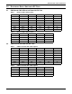
Electrical Data—Units with EC Fans 3.0 ELECTRICAL DATA—UNITS WITH EC FANS 3.1 CW106 and CW114 Electrical Data with EC Fans Table 1 Reheat Humidifier Volts FLA WSA OPD Electric Infrared 460 65.4 81.8 90 Electric Infrared 575 53.4 66.8 70 Electric Infrared 460 53.8 67.3 70 Electric Infrared 575 41.8 52.3 60 None Infrared 460 26.3 32.9 35 None Infrared 575 23.3 29.1 30 None None 460 14.7 15.9 20 None None 575 11.7 12.7 15 Table 2 3.
Dimensional Data 4.0 DIMENSIONAL DATA Figure 1 Dimensions, CW026 - CW084 J Projection of Display Bezel 3/4" (19mm) nsion Overall Dime C D turn Air Re g Openin 2" (50.8mm) Overa A ll D Unit A imension nd Ple num Air Re B turn O penin g 2" (50.8mm) J A Overall Dimens ion C Unit An d Plenu binet m Unit Ca 1" F Plenum (25.4mm) rall on Dimensi Overall Projection of Display Bezel 3/4" (19mm) 1" ) (25.4mm 72" (1829mm) Ove K Air Re B turn O penin g n Air Retur Opening 1" ) (25.4mm 2" (50.
Dimensional Data Figure 2 Dimensional Data—50 & 60 Hz Systems CW106—CW114, downflow models G Overall Dimension Projection of Display Bezel 3/4" (19mm) Overall C D turn Air Re g Openin 2" (50.8mm) Air R A Dimen sion B eturn Open ing G 2" (50.8mm) Overall ion Dimens Projection of Display Bezel 3/4" (19mm) 76" (1930mm) A Overall Dimen sio Unit an d Plenu n m C 1" (25.
Dimensional Data Figure 3 Cabinet and Floor Planning Dimensional Data, Downflow Model CW181 with EC Fans Note: Electrical connections can be made from the bottom of the unit. 118" (2997mm) Opening 47" 39-1/2" (1194mm) (1003mm) Opening 3/4" (19mm) Bezels TOP VIEW 122" (3099mm) 36" (914mm) 24" (610mm) 76" (1930mm) 1-1/2" (38mm) Striated area indicates the recommended minimum clearance for component access.
Dimensional Data Figure 4 Cabinet and floor planning dimensions, upflow models—CW026-CW084 Projection Of Display Bezel 3/4" (19mm) 35-5/8" ) (905mm Overall on Dimensi A Overall Dimen sion 35" m) 8 (8 9m Duct Flanges on 2 Blowers H 1" (25.
Dimensional Data Figure 5 Cabinet and floor planning dimensions, CW 106 and CW114 upflow models Projection of Display Bezel 3/4" (19mm) 2" (51mm) 35" Overall (889mm) 32" (813mm) Plenum Flange 122" Overall (3099mm) 118" (2997mm) Plenum Flange 2" (51mm) 76" (1930mm) 1" (25mm) flange for decorative plenum alignment Flanges provided on blower outlets for supply air ducting.
Upflow Duct Connection Data CW026—CW084 5.0 UPFLOW DUCT CONNECTION DATA CW026—CW084 No. of Blowers Model No. Chilled Water Dimensional Data—in.
Blower Duct & Deck Dimensions, CW106 and CW114, Upflow Models 6.0 BLOWER DUCT & DECK DIMENSIONS, CW106 AND CW114, UPFLOW MODELS Model CW106 Blower Supply Motor, hp Top Front Net Weight lb.
Electrical Specifications 7.0 Table 5 ELECTRICAL SPECIFICATIONS Electrical data—50 Hz systems Reheat Options Electric None Electric None Humidifier Options IR/SGH IR/SGH Steam or None Steam or None Models CW026 CW038 CW041 CW051 CW060 CW076 CW084 CW106 CW114 Motor HP Volts 200 230 380-415 200 230 380-415 200 230 380-415 200 230 380-415 2.0 FLA 46.7 43.4 24.3 19.8 17.2 9.9 33.9 32.3 17.9 7.0 6.1 3.5 3.0 FLA 49.8 46.1 25.9 22.9 19.9 11.5 37.0 35.0 19.5 10.1 8.
Electrical Specifications Table 7 Electrical data—60 Hz Systems Chilled Water Models - 60Hz Reheat Options Humidifier Options Models / Motor HP CW026 CW026 CW038 CW038 CW041 CW041 CW051 CW060 CW076 CW076 CW084 CW084 CW106 CW106 Volts FLA WSA 2.0 HP MFCB FLA WSA 3.0 HP MFCB FLA WSA 3.0 HP MFCB FLA WSA 5.0 HP MFCB FLA WSA 3.0 HP MFCB FLA WSA 5.0 HP MFCB FLA WSA 5.0 HP MFCB FLA 7.5 HP WSA MFCB FLA 5.0 HP WSA MFCB FLA 7.5 HP WSA MFCB FLA 7.5 HP WSA MFCB FLA WSA 10.0 HP MFCB FLA 7.
Electrical Specifications Table 7 Electrical data—60 Hz Systems (continued) Chilled Water Models - 60Hz Reheat Options Humidifier Options Models / Motor HP Volts FLA CW106 20.0 HP WSA (Upflow only) MFCB FLA CW114 10.0 HP WSA MFCB FLA CW114 WSA 15.0 HP MFCB FLA CW114 20.
Guide Specifications GUIDE SPECIFICATIONS 1.0 GENERAL 1.1 Summary These specifications describe requirements for a precision environmental control system. The system shall be designed to maintain temperature conditions in the rooms containing electronic equipment. The manufacturer shall design and furnish all equipment to be fully compatible with heat dissipation requirements of the room. 1.
Guide Specifications System Auto Restart - The auto restart feature will automatically restart the system after a power failure. Time delay is programmable. Sequential Load Activation - On initial startup or restart after power failure, each operational load is sequenced with a minimum of one second delay to minimize total inrush current. Hot Water Flush Cycles - Hot water reheat coils and Econ-O-Coils are periodically flushed to prevent a buildup of contaminants.
Guide Specifications The Service Menus Shall be Defined as Follows Setpoints: Menu shall allow setpoints within the following ranges: • • • • • • • • Temperature Setpoint 65-85ºF (18-29ºC)* Temperature Sensitivity +1-10ºF (0.6-5.
Guide Specifications Advanced Menus Factory Settings: Configuration settings shall be factory-set based on the pre-defined component operation. Change Passwords: Menu shall allow new passwords to be set or changed. 2.4.
Guide Specifications 2.5.1.4 Alarms The Liebert iCOM control shall activate an audible and visual alarm in event of any of the following conditions: • • • • • • • • • High Temperature Low Temperature High Humidity Low Humidity Main Fan Overload (opt) Change Filters Loss of Air Flow Loss of Power Custom Alarm (#1 to #4) Custom alarms are four customer accessible alarm inputs to be indicated on the front panel.
Guide Specifications 2.7 High Pressure Chilled Water Control Valve—Optional The chilled water circuit shall include a 3-way (2-way) high pressure modulating valve. The valve shall be designed for up to 400 PSI (2758 kPa) water pressure. 2.8 A-Frame Chilled Water Coil The cooling coil shall be of A-frame design with a minimum of ____ sq. ft. (sq.m.) face area, ____ rows deep. The coil shall be controlled by a 3-way modulating control valve.
Guide Specifications 2.11.6 Floor Stand The floor stand shall be constructed of a heliarc-welded, tubular steel frame. The floor stand shall have adjustable legs with vibration isolation pads. The floor stand shall be ____ inches high. 2.11.6.1 Floor Stand Turning Vane A factory-supplied, field-mounted turning vane shall be provided. 2.11.6.2 Smoke Sensor The smoke sensor shall immediately shut down the environmental control system and activate the alarm system when activated.
Ensuring The High Availability Of Mission-Critical Data And Applications. Emerson Network Power, the global leader in enabling business-critical continuity, ensures network resiliency and adaptability through a family of technologies—including Liebert power and cooling technologies—that protect and support business-critical systems. Liebert solutions employ an adaptive architecture that responds to changes in criticality, density and capacity.