DISCONTINUED PRODUCT Precision Cooling For Business-Critical Continuity Liebert Deluxe System/3™ - DX Installation Manual - 50 and 60 Hz, 6-30 Ton DX Systems (DH/DE/VH/VE)
DISCONTINUED PRODUCT
TABLE OF CONTENTS PRODUCT MODEL INFORMATION . . . . . . . . . . . . . . . . . . . . . . . . . . . . . . . . . . . . . . . . . . . . . . . . . . V 1.0 INTRODUCTION . . . . . . . . . . . . . . . . . . . . . . . . . . . . . . . . . . . . . . . . . . . . . . . . . . . . . . . . . .1 1.1 System Descriptions . . . . . . . . . . . . . . . . . . . . . . . . . . . . . . . . . . . . . . . . . . . . . . . . . . . . . . . . . . 1 1.1.1 1.1.2 1.1.3 1.1.4 Compressorized Two-Step Systems . . . . . . . . . . . . . . .
.1 Drycooler Location . . . . . . . . . . . . . . . . . . . . . . . . . . . . . . . . . . . . . . . . . . . . . . . . . . . . . . . . . . 36 4.1.1 4.1.2 Outdoor Prop Fan Models . . . . . . . . . . . . . . . . . . . . . . . . . . . . . . . . . . . . . . . . . . . . . . . . . . . . . 36 Indoor Piggyback Models . . . . . . . . . . . . . . . . . . . . . . . . . . . . . . . . . . . . . . . . . . . . . . . . . . . . . . 36 4.2 Drycooler Installation . . . . . . . . . . . . . . . . . . . . . . . . . . . . . .
FIGURES Figure 1 Figure 2 Figure 3 Figure 4 Figure 5 Figure 6 Figure 7 Figure 8 Figure 9 Figure 10 Figure 11 Figure 12 Figure 13 Figure 14 Figure 15 Figure 16 Figure 17 Figure 18 Figure 19 Figure 20 Figure 21 Figure 22 Figure 23 Figure 24 Figure 25 Figure 26 Figure 27 Figure 28 Figure 29 Figure 30 Figure 31 Figure 32 Figure 33 Figure 34 Downflow (DH and DE models) cabinet and floor planning dimensional data . . . . . . . . . . . . . . . .
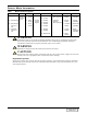
TABLES Table i Table ii Table 1 Table 2 Table 3 Table 4 Table 5 Table 6 Table 7 Table 8 Table 9 Table 10 Table 11 Table 12 Table 13 Table 14 Table 15 Table 16 Table 17 Table 18 Table 19 Table 20 Table 21 Table 22 Table 23 Table 24 Table 25 Table 26 Table 27 Table 28 Table 29 Table 30 Table 31 Table 32 Table 33 Table 34 Table 35 Table 36 Table 37 Model number designation . . . . . . . . . . . . . . . . . . . . . . . . . . . . . . . . . . . . . . . . . . . . . . . . . . . . . . . . . v Unit weights . . . . .
PRODUCT MODEL INFORMATION Table i Model number designation DH 245 A – A A = Air U = 4 Step DX Nominal Cooled Capacity in Thousand DH = Downflow DX BTU/H W = Water H = DX with Cooled Hot gas Bypass DE = Downflow DX G = Glycol w/ Econ-OCooled Coil A = 460/3/60 VE = Upflow DX w/ Econ-OCoil H = 230/3/50 VH = Upflow DX B = 575/3/60 C = 208/3/60 D = 230/3/60 F = 380/3/50 G = 415/3/50 A ! WARNING ! CAUTION 0 = No Humidifier G = Advanced E = Electric I = Infrared Graphics Reheat Humidifier Micro-p
Table ii Unit weights Air Cooled Models DH/VH, 60 (50) Hz Water Cooled Models DH/VH, 60 (50) Hz Glycol Cooled Models DH/VH, 60 (50) Hz GLYCOOL Models DE/VE, 60 (50) Hz Capacity and Cooling Type Weight lbs (kg) 75A 1205 (547) 114A (115A) 1425 (647) 125A (130A) 1440 (645) 199A 1840 (835) 245A 1960 (890) 290A 2025 (920) 380A 2160 (981) 86W 1455 (661) 127W (128W) 1675 (761) 138W (143W) 1690 (768) 219W 2110 (957) 267W 2280 (1036) 315W 2345 (1065) 412W 2500 (1135) 72G 1455 (66
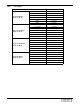
Introduction 1.0 INTRODUCTION 1.1 System Descriptions Deluxe System/3 environmental control systems are available in several configurations. Each configuration can operate with either Advanced Microprocessor Controls (AM), or Advanced Microprocessor Controls with Graphics (AG). A brief description of each, including operational differences, can be found below. Check model numbers to see what is supplied with your unit. 1.1.
Introduction 1.1.3 GLYCOOL™ (Chilled Glycol Cooling) Systems GLYCOOL systems have all of the features of a compressorized water or glycol system, plus a second cooling coil that is connected into the water circuit. When fluid temperature is sufficiently low (below room temperature), cooling is provided by circulating the fluid through the second cooling coil (flow is controlled by a motorized valve.) This is then the primary cooling source, and it greatly reduces the compressor operation.
Installation 2.0 INSTALLATION 2.1 Room Preparation The room should be well-insulated and must have a sealed vapor barrier. The vapor barrier in the ceiling can be a polyethylene film type. Use a rubber-base or plastic-base paint on concrete walls and floors. Doors should not be undercut or have grilles in them. Outside, or fresh, air should be kept to an absolute minimum. Outside air adds to the heating, cooling, humidifying and dehumidifying loads of the site.
Installation 2.3 Unit Dimensions Figure 1 Downflow (DH and DE models) cabinet and floor planning dimensional data SHADED AREAS INDICATE A RECOMMENDED CLEARANCE OF 34 (864mm) FOR COMPONENT ACCESS AND FILTER REMOVAL. FOR RECOMMENDED MINIMUM CLEARANCE, REFER TO THE INSTALLATION MANUAL.
Installation Table 1 Downflow (DH and DE models) dimensions Air Cooled Water Cooled Glycol Cooled GLYCOOL 60 Hz 50 Hz DH75A DH86W DH72G DE72G Dimensional Data inches (mm) A B C D E F G H J K L DH75A DH86W DH72G DE72G 74 (1880) 70 (1778) 35 (889) 32 (813) 72 (1829) 33 (838) 14-1/4 (362) 54-3/4 (1391) 35-5/8 (905) 63-1/2 1613 27 (686) DH114A DH127W DH110G DE110G DH115A DH128W DH111G DE111G 74 (1880) 70 (1778) 35 (889) 32 (813) 72 (1829) 33 (838) 14-1/4 (362) 54-3/4 (1391)
Installation Figure 2 Upflow 6, 8 and 10 ton (VH and VE models) cabinet and floor planning dimensional data UNIT DIMENSIONAL DATA Projection of Display Bezel 5/8" (16mm) 35" overall 74 " (18 ove 80 ral 70 mm l Ple " (1 ) nu 778 m m Fla m) ng e (889mm) 32" (838mm) Plenum Flange 2" (51mm) 2" (51mm) 72" (1829mm) DUCT CONNECTION DATA Models With Rear Return Flange provided on blower outlet for supply air ducting Air grille supplied on units with front return air only 1" (25.
Installation Figure 3 Upflow 6, 8 and 10 ton (VH and VE models) blower duct and deck dimensional data 74" ref (1880mm) Duct Flange on Blower Top of Unit A D 35" ref (889mm) C 72" ref (1829mm) Front of Unit Blower Duct Flange Location Table 2 F Blower Deck B Front or Rear Air Supply DPN000528 Rev0 Upflow 6, 8 and 10 ton (VH and VE models) blower duct and deck dimensional data Blower Supply Motor HP TOP FRONT A B C D F 1-5 22-7/8 (581) 3-1/2 (89) 18-13/16 (478) 16-3/16 (411) 1-1/2
Installation Figure 4 Upflow 15, 20 and 22 ton (VH and VE models) cabinet and floor planning dimensional data Projection of Display Bezel 35" overall (889mm) 5/8" (16mm) 2" (51mm) 32" (838mm) Plenum Flange 99 " (25 ove 15 ral mm l ) UNIT DIMENSIONAL DATA 9 Ple (241 5" nu 3m m m) Fla ng e 2" (51mm) 76" (1930mm) DUCT CONNECTION DATA Models With Rear Return Air grille supplied on units with front return Shaded areas air only indicate a recommended clearance of 34" (864mm) for component access and f
Installation Figure 5 Upflow 15, 20 and 22 ton (VH and VE models) blower duct and deck dimensional data TOP OF UNIT 99" (2514.6) ref. Duct Flanges on Two Blower D C E Blower Deck A 35" (889mm) ref. C 76" (1930.4mm) ref.
Installation Figure 6 Upflow 30 ton (VH and VE models) cabinet and floor planning dimensional data Projection of display bezel 5/8" (16mm) 35" (889mm) Overall 32" (838mm) Plenum Flange 2" (51mm) UNIT DIMENSIONAL DATA 122" (3099mm) Overall 118" (2997mm) Plenum Flange 2" (51mm) 76" (1930mm) DUCT CONNECTION DATA Models With Rear Return Flanges provided on blower outlets for supply air ducting Air grille supplied on units with front return air only Shaded areas indicate a recommended clearance of 34" (8
Installation Figure 7 Upflow 30 ton (VH and VE models) blower duct and deck dimensional data 122" (3098.8) ref. TOP OF UNIT Duct Flanges on Three Blower A D C E G F 35" (889) ref. C E Blower Deck B 76" (1930.
Installation 2.4 Piping All fluid and refrigeration connections to the unit, with the exceptions of the condensate drain and live steam, are sweat copper. Factory-installed piping brackets must not be removed. Field-installed piping must be installed in accordance with local codes and must be properly assembled, supported, isolated and insulated. Avoid piping runs through noise-sensitive areas, such as office walls and conference rooms.
Installation Figure 8 Electrical connection details ROOM UNIT CONNECTIONS NOTES To line voltage components on Liebert room unit electric panel L1 3-phase line voltage supply to line voltage connection block or optional main disconnect switch (Note 2) L2 L3 To line voltage components in Liebert room unit OR Earth ground to ground lug bolt or optional ground bar 37 38 24 50 51 55 56 77 2-wire connection for each Special Alarm (Note 4) 22 ga.
Installation Figure 9 Electrical field connections Field-supplied disconnect switch when factory-installed unit disconnect switch is not provided Factory-installed unit disconnect switch (optional) Monitoring panel 3-phase electric service not by Liebert Field-wired to components on electric panel Electric connection block 3-phase connection; electric service connection terminals when factory disconnect switch is supplied 3-phase connection; electric service connection terminals when factory disconnect
Installation 2.6 Air Distribution Considerations 2.6.1 Raised-Floor Air Flow Distribution Considerations To ensure proper air distribution, any unusual restrictions within the air circuit must be avoided. For under-floor air distribution, observe the following guidelines: Select the air supply grilles and perforated panels for the raised floor to ensure minimum loss of pressure in the circuit.
Installation 2.6.3 Ducted Application Installation Duct flanges are supplied on the blower outlets. Follow the SWACNA-Duct Construction Standard for single-, dual-, or triple-blower systems. Do not run ductwork off the perimeter flange on the top of the unit. This flange is for positioning and attaching the optional air discharge plenum with grill. Attaching a duct to this flange may reduce airflow to inadequate levels. Figure 10 Ducting configurations 2 1 2 2 1 1 1.
Installation Figure 11 Plenum dimensional data for 6 - 22 ton models D C 1" (25mm) NOTE: FLANGES PROVIDED ON BLOWER(S) OUTLET FOR SUPPLY AIR DUCTING WHEN SOLID PANEL PLENUM IS USED. J 1" (25mm) 2" (50mm) 18" (457mm) H 1" (25mm) BOTH TOP DUCT OPENINGS AND FRONT GRILLE ARE SHOWN. SEE SPECIFICATION SHEET FOR SPECIFIC APPLICATION. E B A F 2" (50mm) 1" (25mm) D C 2" (50mm) 1" (25mm) FLANGE IS STANDARD ON ALL UNITS EXCEPT DOWNFLOW (DH/DE) MODELS WHERE IT MUST BE SPECIFIED IF REQUIRED.
Installation Figure 12 Plenum dimensional data for 30 ton models Note: Flanges provided on blower outlet(s) for supply air ducting when solid panel plenum is used 1" (25mm) D C L 18" (457mm) K 1"(25mm) B F G E H J E Both top duct openings and front grilles are shown. See specification sheet for specific application A 1"(25mm) D C 2" (50mm) 2" (50.
Air Cooled Models 3.0 AIR COOLED MODELS 3.1 Condenser Location 3.1.1 Outdoor Prop Fan Models The air cooled condenser should be located for maximum security and maintenance accessibility. Avoid ground level sites with public access or areas that contribute to heavy snow or ice accumulations. Utilize centrifugal condensers whenever interior building locations must be used.
Air Cooled Models 3.3 Refrigerant Piping All refrigeration piping should be installed with high temperature brazed joints. Prevailing good refrigeration practices should be employed for piping supports, leak testing, dehydration and charging of the refrigeration circuits. The refrigeration piping should be isolated from the building by the use of vibration isolating supports. Piping, including inverted trap(s), must be routed to allow unobstructed access to the panel per the NEC.
Air Cooled Models Figure 13 Piping: Fan speed control condensers Returning liquid line (Typ.) Entering hot gas line (Typ.) 10060Pg4 Inverted traps are to be field-supplied and installed (Typ.). When installing traps, clearance must be provided for swing of end access door. Traps are to extend above base of coil by a minimum of 7-1/2" (190mm). Table 9 Fan speed control condenser piping connection sizes - Cu OD Entering Hot Gas Line In. (mm) Returning Liquid Line In. (mm) CDF-065 1/2 (12.7) 1/2 (12.
Air Cooled Models Figure 14 Piping: Lee-Temp control condensers Entering hot gas line (Typ.) Returning liquid line (Typ.) 10061Pg6 Lee-Temp receiver tank Table 10 Lee-Temp control condenser piping connection sizes Lee-Temp Connections-ODS inches (mm) Condenser Connections-ODS inches (mm) Model # Hot Gas A Liquid B Lee-Temp Size Hot Gas Tee F Liq. to L-T Valve C Receiver Out D CDL-065 1/2 (12.7) 1/2 (12.7) (2) W-4 1-1/8 (28.6) 7/8 (22.2) 5/8 (15.9) CDL-083L 1/2 (12.7) 1/2 (12.
Air Cooled Models Figure 15 Downflow air cooled (DH) piping connections MONITORING PANEL NOTE: Install all piping per local codes. Condensate Drain. Field pitch a min. of 1/8" (3.2mm) per ft. (305mm). 3/4" NPT for units without factory installed condensate pump. Do not install an external trap. 1/2" OD CU for units with factory installed condensate pump. C - Steam Reheat Supply Line D - Hot Water Reheat Supply Line.
Air Cooled Models Figure 16 Upflow air cooled (VH) piping connections Install field piping through factorysupplied cover plate (not shown for clarity). Unit Left End Seal around all Panel piping penetrations.
Air Cooled Models Figure 17 Outdoor air cooled 1-4 fan condenser cabinet and anchor dimensional data Eyebolts for lifting condenser provided on four-fan models only 43-9/16" (1107mm) A 70" (1778mm) Height to top 37-7/8" of fan guard 43-1/8" (962mm) (1095mm) 18" (457mm) Optional disconnect switch handle 43-3/16" (1097mm) B Clearance of 36" (914.4mm) recommended on all sides for proper operation and component access SL-18200-03-01 1" (25.4mm) 1-3/4" (44.5mm) 4-1/4" (108mm) B C 1-3/4" (44.
Air Cooled Models Table 13 Outdoor air cooled 1-4 fan condenser physical data Total Heat CFM Rejection 50 Hz3 CFM Net (l/s) (l/s) Weight Model # of CSF/CDF1 Fans in. (mm) in. (mm) in. (mm) in. (mm) BTU/H/°F kW/°C 60 Hz2 BTU/H/°F kW/°C 50 Hz2 lb (kg) A B C D Total Heat Rejection 60 Hz3 -065 1 51-1/2 (1308) 44 (1118) 42 (1067) _ 1464 .772 6866 (3240) 1349 .712 5722 (2700) 295 (134) -083L 1 51-1/2 (1308) 44 (1118) 42 (1067) _ 1655 .873 6000 (2831) 1526 .
Air Cooled Models Figure 18 Outdoor air cooled 6 and 8 fan condenser cabinet and anchor dimensional data NOTE: Refer to sheet 10067 Pg. 4 for connection sizes Recommended rigging and spreader bars required for installation; rigging and bars not supplied by Liebert Location of holes and support for rigging (typ. 4) 87-1/8" (2213mm) L Height to top of fan guard 43-1/8" (1095mm) 37-7/8" (962mm) Optional disconnect switch handle Center leg provided on 8-fan models only 86-3/4" (2203.5mm) 1" (25.
Air Cooled Models Figure 19 Air cooled model general arrangement diagram Condenser Coil Schrader Valve Fusible Plug Inverted traps* on discharge and return lines to extend above base of coil by a minimum of 7-1/2" (190mm) Evaporator Coil Traps* every 25ft. (7.
Air Cooled Models Figure 20 Piggyback condenser cabinet and floor planning dimensional data 1 1/8" (29mm) E K H J D B R Dime Overall K Overa ll Dim e nsio nsions ns OPTIONAL FAN DISCHARGE S DISCONNECT SWTICH (OPTIONAL) H J R 35 1/8" (892mm) 72" (1829mm) FAN DISCHARGE SHADED AREAS INDICATE A RECOMMENDED CLEARANCE OF 34" (864mm) FOR COMPONENT ACCESS. 5" (127mm) 1" (25.
Air Cooled Models Figure 21 Piggyback condenser piping connections SEE NOTE 2 SEE NOTE 1 SEE NOTE 1 SEE NOTE 2 1 13/16" (46mm) B A NOTES: C G 1 13 16" (46mm) 1. Multiple K.O. of 1 3/8" (35mm), 1 3/4" (45mm) and 2 1/2" (64mm) for main power supply (typ.). 2. 7/8" (22.2mm) K.O. for Lee-Temp power supply (typ.). 3. Cover plate for access of liquid line and hot gas line.
Air Cooled Models 3.4 Fan Speed Control Systems Fan Speed Control provides an infinite number of speed variations on specially designed permanent split-capacitor motors. The control module varies the air quantity passing over the condenser coil by monitoring refrigerant pressure. 3.4.1 3.4.
Air Cooled Models Table 19 Indoor unit approximate refrigerant charge lb (kg.) R–22 Model 60 Hz (50 Hz) Refrigerant Charge/Circuit 75A 4.0 (1.8) 114A (115A) 5.0 (2.3) 125A (130A) 5.0 (2.3) 199A 6.0 (2.7) 245A 7.0 (3.2) 290A 7.0 (3.2) 380A 8.0 (3.6) Table 20 Outdoor condenser approximate refrigerant charge lb (kg) per circuit Model Fan Speed Control Lee-Temp (Includes Receiver) 097 108 130 5 (2.3) 6 (2.7) 5 (2.3) 27 (12.3) 33 (15.0) 27 (12.
Air Cooled Models 3.5 Lee-Temp/Flood Back Head Pressure Control Systems The Lee-Temp system consists of a modulating type head pressure control valve and insulated receivers with heater pads to ensure operation at ambient temperatures as low as -30°F (-34.4°C). 3.5.1 Piping Be sure to install the valve with the refrigerant flow in the proper direction.
Air Cooled Models 3.5.4 3.5.5 Charging 1. Make sure unit is OFF and that jumper is removed on Fan Safety Switch. 2. Connect a set of manifold gauges to the refrigerant drum and to the receiver at the rotalock valve. Purge the hoses. 3. Open the rotalock valve and fill the receiver with liquid refrigerant per Table 26. 4. Close the valve and disconnect gauges. 5. Start the compressor and recheck the refrigerant level. If the level has dropped, recharge with vapor through the suction port. 6.
Air Cooled Models Figure 23 Lee-Temp control typical general arrangement diagram Condenser Coil Inverted traps* on discharge and return lines to extend above base of coil by a minimum of 7-1/2" (190mm) Piping Assembly** Rotalock Valve** Check Valve Head Pressure Control With Integral Check Valve 1/4" (6.4mm) Pressure Relief Valve** Lee-Temp Receiver Sight Glass Evaporator Coil Liquid Return from Condenser Traps* every 25’ (7.
Glycol Cooled/GLYCOOL™ Models 4.0 GLYCOL COOLED/GLYCOOL™ MODELS 4.1 Drycooler Location 4.1.1 Outdoor Prop Fan Models The drycooler should be located for maximum security and maintenance accessibility. Avoid groundlevel sites with public access or areas that contribute to heavy snow or ice accumulations. To assure adequate air supply, it is recommended that drycoolers be located in a clean air area, away from loose dirt and foreign matter that may clog the coil.
Glycol Cooled/GLYCOOL™ Models Table 23 Room dew point temperatures °F (°C) Dry Bulb Wet Bulb Relative Humidity Dew Point 70 (21.1) 57.2 (14.0) 45 48.9 (8.9) 70 (21.1) 58.5 (14.7) 50 50.5 (10.3) 72 (22.2) 58.9 (14.9) 45 50.0 (10.0) 72 (22.2) 60.0 (15.5) 50 52.4 (11.3) 75 (23.8) 61.2 (16.2) 45 52.4 (11.3) 75 (23.8) 62.5 (16.9) 50 55.0 (12.7) *Minimum glycol temperature before condensation will occur.
Glycol Cooled/GLYCOOL™ Models Figure 24 Downflow glycol cooled (DH) piping connections MONITORING PANEL NOTE: Install all piping per local codes. C - Steam Reheat Supply Line D - Hot Water Reheat Supply Line. A - Glycol Return Line. 3/4" NPT Condensate Drain. Field pitch a min. of 1/8" (3.2mm) per ft. (305mm). Do not install an external trap. E - Steam Reheat Return Line (Field install factory supplied steam trap with vacuum breaker). F - Hot Water Reheat Return Line.
Glycol Cooled/GLYCOOL™ Models Figure 25 Upflow glycol cooled (VH) piping connections Install field piping through factory-supplied cover plate (not shown Unit for clarity). Seal around Left all piping penetrations.
Glycol Cooled/GLYCOOL™ Models Figure 26 Downflow GLYCOOL™ cooled (DE) piping connections MONITORING PANEL NOTE: Install all piping per local codes. A - Glycol Return Line. 3/4" NPT Condensate Drain. Field pitch a min. of 1/8" (3.2mm) per ft. (305mm). Do not install an external trap. 1/4" OD CU Humidifier Supply Line Steam Gen./Infrared) B - Glycol Supply Line.
Glycol Cooled/GLYCOOL™ Models Figure 27 Upflow GLYCOOL™ cooled (VE) piping connections UNIT CONNECTION LOCATIONS Piping stubbed out inside unit end compartment for field connection through 2 3/8" x 16" (60.3 x 406mm) opening as shown. Piping is recessed inside the unit and not flush as indicated. Piping may also exit through bottom of end compartment by field cutting an opening in a suitable location (except bottom return air units). 1" (25.4mm) REAR PANEL 7/8" (22.2mm) 2 3/8" (60.
Glycol Cooled/GLYCOOL™ Models Figure 28 1-4 fan drycooler cabinet and anchor dimensional data Eyebolts for lifting condenser provided on four-fan models only Inlet Connection (upper header) A 70" Outlet (1778mm) 43-9/16" (1107mm) Connection (lower header) Height to top of fan guard 43-1/8" 37-7/8" (962mm) (1095mm) 4" (101.6mm) Disconnect Switch Handle 43-3/16" (1097mm) 18" (457mm) Clearance of 36" (914.4mm) recommended on all sides for proper operation and component access B EXPANSION TANK 11.
Glycol Cooled/GLYCOOL™ Models Table 33 1-4 fan drycooler physical data # of (Notes 2,3,4) Fans Model A B C D in. (mm) in. (mm) in. (mm) in. (mm) Piping Connection Sizes CFM (l/s) 60 Hz1 CFM (l/s) 50 Hz1 Internal Volume gal. (l) Net Weight lb (kg) Inlet in. (mm) Outlet in. (mm) -033 1 51-1/2 (1308) 44 (1118) 42 (1067) _ 7200 (3398) 6000 (2932) 1.2 (4.6) 390 (177) 3/4 (19.1) 3/4 (19.1) -069 1 51-1/2 (1308) 44 (1118) 42 (1067) _ 6866 (3240) 5722 (2700) 2.4 (9.
Glycol Cooled/GLYCOOL™ Models Figure 29 6- and 8-fan drycooler cabinet and anchor dimensional data Recommended rigging and spreader bars required for installation; rigging and bars not supplied by Liebert NOTE: Refer to sheet 10067 Pg. 4 for connection sizes Location of holes and support for rigging (typ. 4) 87-1/8" (2213mm) L Height to top of fan guard 43-1/8" 37-7/8" (1095mm) (962mm) Optional disconnect switch handle 86-3/4" (2203.5mm) 1-3/4" (44.5mm) 1" (25.
Glycol Cooled/GLYCOOL™ Models 4.5 Preparation of Glycol Solutions Typical ethylene glycol manufacturers and suppliers are Union Carbide (Ucartherm) or Dow Chemical Company (Dowtherm SR-1). These ethylene glycols are supplied with an inhibitor and do not contain an anti-leak formula. NOTE For glycol solution preparation and periodic testing, follow manufacturer's recommendations. Do not mix products of different manufacturers. ! CAUTION Automotive antifreeze is unacceptable and must NOT be used.
Glycol Cooled/GLYCOOL™ Models Figure 30 Glycol general arrangement Expansion Tank field-installed at highest point in system Drycooler Electric Box Fill* Optional Dual Pump System Shown Unions* Drycooler Coil Pump Housing Check Valves * (dual Fluid pump systems only) Unions* Return to Gate Valves* Pump Fluid Evaporator Pressure Ports* Supply Coil Hose from Aquastat Bibs* Pump Sensing Flow Switch supplied Air Vents* Bulbs Expansion with dual pump systems at top of Valve risers Solenoid Valves Flow Regu
Glycol Cooled/GLYCOOL™ Models Figure 31 GLYCOOL™ general arrangement Fill* Expansion Tank field-installed at highest point in system Drycooler Electric Box Glycol Pumps Unions* Drycooler Coil Optional Dual Pump System Shown Pump Housing Gate Valves* Check Valves * (dual pump systems only) Fluid Return Flow Switch to Pump supplied with dual pump Fluid Supply from Pump systems Hose Bibs* Aquastat Sensing Air Vents* Bulbs at top of risers Econ-O-Coil Pressure Ports* Valve Actuator Econ-O-Cycle
Water Cooled Models 5.0 WATER COOLED MODELS 5.1 Piping Considerations Manual shut-off valves should be installed at the supply and return lines of each unit. This will provide for routine maintenance or emergency isolation of the unit. When the water source for the condenser is of poor quality, it is good practice to provide cleanable filters in the supply line. These filters will trap the particles in the water supply and extend the service life of the water-cooled condenser.
Water Cooled Models Figure 32 Water cooled general arrangement Evaporator Coil Sensing Bulb Single Refrigeration Circuit Shown Solenoid Valves Expansion Valve Sight Glass Filter Dryer Shutoff Valve Water Coolant Circuit (one required per unit) Fluid Fluid Supply Return from Unit to Unit Shutoff Valves* Muffler Service Valves Liquid Return Bypass Valves (optional) External Equalizers Cylinder Unloader (optional) Hot Gas Bypass Valve Hot Gas Bypass (optional) Hot Gas Reheat Coil (optional on down
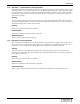
Water Cooled Models Figure 33 Downflow water cooled (DH) piping connections MONITORING PANEL NOTE: Install all piping per local codes. C - Steam Reheat Supply Line D - Hot Water Reheat Supply Line. E - Steam Reheat Return Line (Field-install factory-supplied steam trap with vacuum breaker) A - Condenser Water Return Line. 3/4" NPT Condensate Drain. Field pitch a min. of 1/8" (3.2mm) per ft. (305mm). Do not install an external trap. F - Hot Water Reheat Return Line.
Water Cooled Models Figure 34 Upflow water cooled (VH) piping connections (22.2mm) Optional Steam Humidifier Install field Unit piping Left End Panel through factorysupplied cover plate (not shown for clarity). Seal around all piping penetrations. Optional Steam Reheat See Figure 37 for piping connecton sizes.
Water Cooled Models Table 37 Factory-provided piping connection sizes, inches, upflow water cooled (VH) Water Cooled Models 50 Hz 60 Hz A OD Cu B OD Cu C NPT FEMALE D OD Cu E NPT FEMALE F OD Cu VH-086W VH-086W 1-5/8 1-5/8 1/2 5/8 1/2 5/8 VH-128W VH-127W 1-5/8 1-5/8 1/2 5/8 1/2 5/8 VH-143W VH-138W 1-5/8 1-5/8 1/2 5/8 1/2 5/8 VH-219W VH-219W 2-1/8 2-1/8 3/4 7/8 3/4 7/8 VH-267W VH-267W 2-1/8 2-1/8 3/4 7/8 3/4 7/8 VH-315W VH-315W 2-1/8 2-1/8 NA NA NA NA
Water Cooled Models NOTES 53 DISCONTINUED PRODUCT
Water Cooled Models 54 DISCONTINUED PRODUCT
DISCONTINUED PRODUCT
Ensuring The High Availability 0f Mission-Critical Data And Applications. Emerson Network Power, the global leader in enabling business-critical continuity, ensures network resiliency and adaptability through a family of technologies—including Liebert power and cooling technologies—that protect and support business-critical systems. Liebert solutions employ an adaptive architecture that responds to changes in criticality, density and capacity.