AC Power For Business-Critical Continuity™ Liebert® MPX™ User Manual–Global Applications
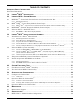
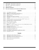
TABLE OF CONTENTS IMPORTANT SAFETY INSTRUCTIONS . . . . . . . . . . . . . . . . . . . . . . . . . . . . . . . . . . . . . . . . . . . . . . . .1 Save These Instructions . . . . . . . . . . . . . . . . . . . . . . . . . . . . . . . . . . . . . . . . . . . . . . . . . . . . . . . . . . . . . . . 1 1.0 LIEBERT® MPX™ INTRODUCTION . . . . . . . . . . . . . . . . . . . . . . . . . . . . . . . . . . . . . . . . . . . .3 2.0 LIEBERT® MPX™ SYSTEM MODULES . . . . . . . . . . . . . . . . . . . . . . . . . . . . . .
7.2 MPX™ PEM™—Model Number Configuration . . . . . . . . . . . . . . . . . . . . . . . . . . . . . . . . . . . . 27 7.3 MPX™ BRM™—Model Number Configuration. . . . . . . . . . . . . . . . . . . . . . . . . . . . . . . . . . . . 28 7.4 MPX™ IPC™—Model Number Configuration. . . . . . . . . . . . . . . . . . . . . . . . . . . . . . . . . . . . . 30 7.5 Agency Approvals . . . . . . . . . . . . . . . . . . . . . . . . . . . . . . . . . . . . . . . . . . . . . . . . . . . . . . . . . . . 31 8.
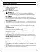
IMPORTANT SAFETY INSTRUCTIONS MPX™ PRC™: Power Rail Chassis MPX PEM™: Power Entry Module MPX BRM™: Branch Receptacle Module MPX IPC™: Input Power Cord MPX RPC™: Rack PDU Card SAVE THESE INSTRUCTIONS ! WARNING Risk of arc flash and electric shock. Can cause equipment damage, injury or death. The Liebert® MPX contains hazardous voltage. Follow the warnings and cautions in this document to avoid serious injury or death from electric shock. Read This Manual This manual contains important safety instructions.
Do Not Open Covers or Insert Objects Never open or remove the cover of any Liebert® MPX™ module, with exception of the Liebert RPC™ cover on the MPX PEM module. Never insert any foreign object into a Liebert MPX, particularly into the power bus. Never insert any foreign object into an MPX PEM™. An exception is that the MPX RPC provides a small hole between the display and sensor RJ-45 connectors to reset the card. See Figure 4 to find the hole location.
Liebert® MPX™ Introduction 1.0 LIEBERT® MPX™ INTRODUCTION The Liebert MPX is an Adaptive Rack PDU (power distribution unit) built with modular and scalable components that can be installed and reconfigured on-site to meet varying input and output power connectivity needs. The flexibility of the modules requires that the installer ensure that the modules match the power requirements of the application. Failure to do so could result in damage to the Liebert MPX and connected components.
Liebert® MPX™ System Modules 2.0 LIEBERT® MPX™ SYSTEM MODULES 2.1 MPX PRC™—Power Rail Chassis/Power and Communication Bus The MPX PRC acts as the fundamental building block of the Liebert MPX. Power and Communications buses are integrated into the full length of the MPX PRC. The MPX BRM™ (Branch Receptacle Modules) and MPX PEM™ (Power Entry Module) lock onto the MPX PRC, adding power input, power output, monitoring and management, depending on the type of module.
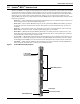
Liebert® MPX™ System Modules Figure 2 MPX PRC™ (Power Rail Chassis) components Section of MPX PRC (Power Rail Chassis) Power Bus Communication Bus Module Connector Slot 2.1.1 PRC1880 installed in Knurr® Miracel™ Mounting Features The back of the MPX PRC features T-slots running the length of the unit. These may be used for mounting the assembled units in racks, such as the Knurr® Miracel™ rack.
Liebert® MPX™ System Modules 2.2 MPX™ PEM™—Power Entry Module/ Power Input ! WARNING Risk of arc flash and electric shock. Can cause equipment damage, injury or death. The MPX PEM contains hazardous voltage. This unit must be properly and securely installed on the MPX PRC (Power Rail Chassis). The power conductors on the bottom of the MPX PEM are energized with hazardous voltage whenever the MPX PEM is attached to power. If the MPX PEM is not installed on the MPX PRC, these conductors will be exposed.
Liebert® MPX™ System Modules Figure 4 MPX PEM™ (Power Entry Module) features Integral Connector Torx Screw Phase Power Indicators Liebert RPC™ Reset Access Hole Alarm Silence/Test Button Liebert RPC Installed in Slot Hard-Wired Power Input Cable Quick-Connect Power Couplings Integral Connector Torx Screw 2.2.
Liebert® MPX™ System Modules 2.3 MPX BRM™—Branch Receptacle Module (Power Output) The MPX BRM provides output power distribution to user load equipment. All MPX BRMs include output receptacles (NEMA, Schuko or IEC) that are overload-protected by 100% rated hydraulicmagnetic circuit breakers. MPX BRMs are hot-swappable to allow user installation without powering down the Liebert MPX.
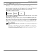
Liebert® MPX™ System Modules Figure 6 MPX BRM™ (Branch Receptacle Module) Receptacles Receptacle On/ Off Indicators (Receptacle Management Units Only) Branch-Rated Circuit Breaker (100% Rated) Integral Connector 2.4 Branch Numeric Indicator Liebert® RPC™—Rack PDU Card The Liebert RPC centralizes local and remote management for the Liebert MPX™. It provides Web and SNMP management for systems connected to an Ethernet network.
Liebert® MPX™ System Modules 2.4.1 RPCBDM™—RPC Basic Display Module The optional RPCBDM provides local display of monitored data for all connected Liebert MPX™ and Liebert MPH™ systems. Display information is accessed via a navigation switch on the RPCBDM. The RPCBDM is cable-connected to the Liebert RPC allowing the user to locate the display to suit the local reading requirements. A 2-meter cable and general mounting provisions are provided.
Liebert® MPX™ Installation and Assembly 3.0 LIEBERT® MPX™ INSTALLATION AND ASSEMBLY All configuration steps must be completed before attempting to startup equipment connected to the Liebert MPX. 3.1 Installation in a Knurr® Miracel Rack Emerson recommends installing the MPX PRC™ (Power Rail Chassis) in the rack, then attaching the Liebert MPX modules to it. Before beginning, consider how cables will be routed in the rack.
Liebert® MPX™ Installation and Assembly 3.1.3 Prepare the Liebert® MPX™ for Mounting 1. Insert two spring nuts into the T-slot on the back of the MPX PRC™, one near either end (see Figure 9 for how to insert a spring nut). 2. Position the spring nuts where the brackets to be used will be positioned (either the Z-shaped or L-shaped brackets). To move a spring nut, press down on it with a small, pointed object and slide it into position. 3.
Liebert® MPX™ Installation and Assembly 3.1.5 Attach L-Shaped Brackets to an Upright Frame Member of the Knurr® Miracel™ 1. Insert two spring nuts into the T-slot on a rear upright frame member (see Figure 11). 2. Position the spring nuts to accommodate screws inserted through slots in the brackets. To move the spring nuts, press down on each with a small, pointed object and slide each into position. 3. Hold an L-shaped bracket in place and attach it with two of the M5x10 screws with hex heads. 4.
Liebert® MPX™ Installation and Assembly 3.2 Liebert® MPX™ System Assembly 3.2.1 Attach an MPX PEM™ or MPX BRM™ to the MPX PRC™ ! WARNING Risk of arc flash and electric shock. Can cause equipment damage, injury or death. This unit must be properly and securely installed on the MPX PRC (Power Rail Chassis). Emerson strongly recommends that the MPX PEM be installed only by an individual who has been properly trained and qualified to perform electrical work.
Liebert® MPX™ Installation and Assembly Disconnect Loads Before Adding or Removing an MPX™ BRM™ During normal operation, MPX BRMs (Branch Receptacle Modules) are hot-swappable. While adding or removing an MPX BRM, no user loads can be connected to the MPX BRM. Attempting to do so may damage the Liebert® MPX™ or connected equipment. To attach either the MPX PEM™ or a MPX BRM: 1.
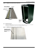
Liebert® MPX™ Installation and Assembly Figure 14 Liebert® MPX™ assembled MPX PRC™ (Power Rail Chassis) (under modules) MPX BRMs™ (Branch Receptacle Modules) Liebert RPC™ (Rack PDU Card) MPX PEM™ (Power Entry Module) 16
Liebert® MPX™ Installation and Assembly 3.2.2 Attach an MPX™ IPC™ to an MPX PEM™—Variable-Capacity MPX PEM Only (North American Models Only) ! WARNING Risk of arc flash and electric shock. Can cause equipment damage, injury or death. The MPX PEM contains hazardous voltage that could cause serious injury or death. This unit must be properly and securely installed on the MPX PRC™ (Power Rail Chassis).
Liebert® MPX™ Installation and Assembly 3.3 Temperature/Humidity Sensor Installation—Optional Optional Liebert® SN temperature/humidity sensors are available to assist in monitoring conditions in the rack. Liebert SN sensors are designed for installation in a Knurr® Miracel™ without tools, but each may be placed in any area to monitor temperature and humidity levels. Each connects to the Liebert RPC™, which makes readings available to Liebert MPX™ monitoring methods.
Liebert® MPX™ Installation and Assembly Install an Optional RPCBDM™ in the Rack 3.4 The RPCBDM (Basic Display Module) can be mounted in the rack with either the included hardware or with a cable tie through the slot on the back of the module (see Figure 17). Either method permits moving the RPCBDM to a different place in the same rack or to another rack. 3.4.1 Mounting Hardware • • • • Spring nut M5: 1 Spacer sleeve: 1 Special MPX screw: 1 Cable clip: 1 Tools Required • Flat-blade screwdriver 3.4.
Liebert® MPX™ Installation and Assembly Figure 18 RPCBDM™ cable connection port on Liebert® RPC™ RPCBDM cable connection port on Liebert RPC 20
System Functional Test 4.0 SYSTEM FUNCTIONAL TEST 4.1 Checklist for Liebert® MPX™ Assembly Follow these guidelines steps to verify that all components are properly assembled. Failure to follow these steps and in the documented sequence could result in a serious injury or equipment damage. ___ 1. MPX PRC™ (Power Rail Chassis) is securely attached to the rack. ___ 2. MPX PEM™ (Power Entry Module) is attached to the MPX PRC. Ensure that the MPX PEM is securely locked onto the MPX PRC. ___ 3.
Operation and Configuration 5.0 OPERATION AND CONFIGURATION A Liebert® MPX™ can be operated with or without the optional Liebert RPC™ (Rack PDU Card). The card employs a Web-based interface to enhance monitoring and control, enabling users to manage rack equipment locally or from a remote location. The Liebert RPC can be used to determine power usage, switch receptacles on some units On and Off and troubleshoot input power supply problems.
Operation and Configuration 5.1.1 Indicators NOTE Do not continue to use the Liebert® MPX ™if the LED panel or monitoring interface indicators are not in accordance with these operating instructions. Refer all faults to your local dealer, Emerson representative or Emerson Distributed Processing Applications Engineering. One or more Phase Power Indicators on the MPX PEM™ (Power Entry Module) should be green and lit but not flashing to indicate that input power is present and within tolerance.
Operation and Configuration 5.2.2 Viewing PDU and Receptacle Status: PDU Explorer and Device Explorer The PDU Explorer permits browsing components from the highest level of the Liebert® MPX™ to the receptacle level. The PDU Explorer is Web-based software that displays a hierarchical view of the system. Using PDU Explorer, the user is able to browse components starting at the PDU level, through to the branches of the PDU, and down to the receptacles of those branches.
Maintenance 6.0 MAINTENANCE The Liebert® MPX™ needs little or no maintenance. Emerson® recommends setting up a maintenance schedule that includes: • Dust the unit’s exterior with a clean, dry cloth. • Check all fittings and connections to ensure they are tight. • If any fuses need replacing, they must be replaced with the same type. 6.1 Maintenance Support The Liebert MPX contains no user-serviceable parts.
Specifications 7.0 SPECIFICATIONS 7.1 MPX™ PRC™—Model Number Configuration • Prefix: MPXPRC• Mounting: V = Vertical • Length: 1035 = Short (40-3/4"; 1035mm); 1880 = Standard (74"; 1880mm) Table 1 MPX PRC (Power Rail Chassis) specifications Maximum Modules Ratings Model # Length, mm (U.) BRM (266mm) PEM MPXPRC-V1880xxx 1880 (42) 6 (266mm) 1 (220mm) MPXPRC-V1035xxx 1035 (23) 3 (266mm) 1 (266mm) 26 Ampere, A Voltage, V 63 240/415 Weight, lb. (kg) 4.76 (2.16) 2.62 (0.
Specifications 7.
Specifications MPX™ BRM™—Model Number Configuration 7.
Specifications Table 3 MPX BRM (Branch Receptacle Module) specifications (continued) Model # Type Receptacle Ratings No. of Outlets Ampere, A Voltage, V OCB, A Voltage Configuration Length, mm Region Weight lb. (kg) BRANCH MONITORING MODULES North American Applications MPXBRM-NBBA6A1N NEMA 5-20R 6 16 120 20 L1-N 266 NA 2.3 (1.03) MPXBRM-NBBA6A2N NEMA 5-20R 6 16 120 20 L2-N 266 NA 2.3 (1.03) MPXBRM-NBBA6A3N NEMA 5-20R 6 16 120 20 L3-N 266 NA 2.3 (1.
Specifications Table 3 MPX BRM (Branch Receptacle Module) specifications (continued) Receptacle Ratings Type No. of Outlets Ampere, A MPXBRM-EEBC3P1N Schuko CEE 7/4 3 16 230 20 L1-N 266 EU 2.3 (1.03) MPXBRM-EEBC3P2N Schuko CEE 7/4 3 16 230 20 L2-N 266 EU 2.3 (1.03) MPXBRM-EEBC3P3N Schuko CEE 7/4 3 16 230 20 L3-N 266 EU 2.3 (1.03) MPXBRM-EEBC4O1N IEC C19 Sheet J 4 16 230 20 L1-N 266 EU 2.3 (1.03) MPXBRM-EEBC4O2N IEC C19 Sheet J 4 16 230 20 L2-N 266 EU 2.
Specifications 7.5 Agency Approvals 120V and 240V Single-Phase and 120/208-240V Three-Phase North American Units • UL60950-1: Information Technology Equipment - Safety, Part 1 General Requirements • CSA C22.2 No. 60950-1: Information Technology Equipment - Safety, Part 1 General Requirements • FCC, Title 47, Part 15 Subpart B for Class B operation as defined by ANSI Standard C63.4.
Dimensional Drawings 8.0 DIMENSIONAL DRAWINGS Figure 21 Liebert® MPX™ assembly dimensions, 1880mm (74") versions 10.5" (266mm) MPX PRC Cover/Spacer 10.5" (266mm) 10.5" (266mm) 10.5" (266mm) 10.5" (266mm) 10.5" (266mm) 74" (1880mm) TOP VIEW 2.9" (75mm) 4.1" (104mm) Input Power Cord 2.9" (75mm) END VIEW 4.
Dimensional Drawings Figure 23 RPCBDM™ dimensions Top Mounting Slot Communication Connection 2.6" (66mm) Rear LCD Screen 0.8" (21mm) 4.5" (116mm) 1.1" (29mm) FRONT VIEW SIDE VIEW 0.787" (20mm) 0.063" (1.6mm) 0.059" (1.5mm) 0.122" (3.1mm) 0.472" (12.
Recycling Information, FCC Compliance, Modifications 9.0 RECYCLING INFORMATION, FCC COMPLIANCE, MODIFICATIONS Notice to European Union Customers: Disposal of Old Appliances This product has been supplied from an environmentally aware manufacturer that complies with the Waste Electrical and Electronic Equipment (WEEE) Directive 2002/96/CE. This product uses components that are dangerous for the environment, such as electronic cards and other electronic components.
Ensuring The High Availability Of Mission-Critical Data And Applications. Emerson Network Power, a business of Emerson (NYSE:EMR), is the global leader in enabling Business-Critical Continuity™ from grid to chip for telecommunication networks, data centers, health care and industrial facilities.