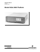
Instruction Manual 760006-A September 2001 Model NGA 2000 Platform http://www.processanalytic.
ESSENTIAL INSTRUCTIONS READ THIS PAGE BEFORE PROCEEDING! Rosemount Analytical designs, manufactures and tests its products to meet many national and international standards. Because these instruments are sophisticated technical products, you MUST properly install, use, and maintain them to ensure they continue to operate within their normal specifications.
Instruction Manual Model NGA 2000 Platform 760006-A September 2001 TABLE OF CONTENTS PREFACE...........................................................................................................................................P-1 Intended Use Statement.....................................................................................................................P-1 Definitions .......................................................................................................................
Instruction Manual 760006-A September 2001 3-0 3-1 3-2 3-3 3-4 3-5 3-6 4.0 4-1 4-2 ii Model NGA 2000 Platform OPERATION ............................................................................................................................3-1 Overview...................................................................................................................................3-1 Display & Operating Keys ..........................................................................................
Instruction Manual Model NGA 2000 Platform 760006-A September 2001 7-0 7-1 7-2 7-3 7-4 7-5 7-6 MAINTENANCE AND SERVICE ...........................................................................................7-1 Maintenance Overview.............................................................................................................7-1 Fuse Replacement ...................................................................................................................
Instruction Manual 760006-A September 2001 Model NGA 2000 Platform LIST OF ILLUSTRATIONS Figure 1-1. Figure 1-2. Figure 1-3. Figure 1-4. Figure 1-5. Figure 1-6. Figure 1-7. Figure 1-8. Figure 1-9. Figure 1-10. Figure 1-11. Figure 1-12. Figure 1-13. Figure 1-14. Figure 3-1. Figure 3-2. Figure 3-3. Figure 3-4. Figure 3-5. Figure 3-6. Figure 3-7. Figure 3-8. Figure 3-9. Figure 3-10. Figure 3-11. Figure 3-12. Figure 3-13. Figure 4-1. Figure 4-2. Figure 4-4. Figure 4-5. Figure 4-6. Figure 4-7. Figure 4-8.
Instruction Manual Model NGA 2000 Platform Figure 6-7. Figure 6-8. Figure 6-9. Figure 6-10. Figure 6-11. Figure 6-12. Figure 6-13. Figure 6-14. Figure 6-15. Figure 6-16. Figure 11-1. Figure 11-2. Figure 11-3. Figure 11-4. 760006-A September 2001 Setting Security Codes .................................................................................................6-8 Network Module Management – List of Active Modules...............................................
Instruction Manual 760006-A September 2001 vi Contents Model NGA 2000 Platform Rosemount Analytical Inc.
Instruction Manual 760006-A September 2001 Model NGA 2000 Platform PREFACE INTENDED USE STATEMENT The purpose of this manual is to provide information concerning the components, functions, installation and maintenance of the NGA 2000 Platform and the System Accessories of the NGA 2000 System. Some sections may describe equipment not used in your configuration. The user should become thoroughly familiar with the operation of this module before operating it. Read this instruction manual completely.
Instruction Manual 760006-A September 2001 Model NGA 2000 Platform SAFETY SUMMARY If this equipment is used in a manner not specified in these instructions, protective systems may be impaired. DANGER. ELECTRICAL SHOCK HAZARD Do not operate without doors and covers secure. Servicing requires access to live parts which can cause death or serious injury. Refer servicing to qualified personnel.
Instruction Manual 760006-A September 2001 Model NGA 2000 Platform DOCUMENTATION The following NGA 2000 Platform instruction materials are available. Contact Customer Service Center or the local representative to order.
Instruction Manual 760006-A September 2001 Model NGA 2000 Platform GLOSSARY OF TERMS 30 A Bulk Power Supply A power supply that is mounted in an enclosure capable of supplying power (+24 VDC @ 30 Amperes) to up to ten Analyzer modules installed in the NGA 2000 System. AK A serial interface protocol, popular in Europe in the automotive industry. AMSN Network variable name containing the module Serial number. This should be the same as the number physically marked on the unit.
Instruction Manual Model NGA 2000 Platform 760006-A September 2001 Control module A Platform containing a Controller computer, a display and a keyboard. Used to view Analyzer data, and configure and troubleshoot the entire NGA 2000 system. Controller Board The Controller Board in the Platform which runs the software program that operates the Display, Keypad and Network Manager. The Controller Board plugs into the Backplane from the Platform front.
Instruction Manual 760006-A September 2001 Model NGA 2000 Platform Info Refers to the help screens in the menu system. Inrush Current Limiting It is sometimes necessary to limit the current drawn by a piece of electronics when it is first switched on. Special devices are available to do this. The NGA 2000 multi-module power supply uses them. IR Infra-red, also short for NDIR or Non-dispersive Infra-red Analyzer.
Instruction Manual Model NGA 2000 Platform 760006-A September 2001 Polynomial A mathematical term meaning an expression (a function of a variable) containing several terms, each of which contains a power of the variable. A + B X x + C X (x X x) is a second order polynomial in x. A,B and C are its zeroth, first and second coefficients. "X" means multiply, as usual.
Instruction Manual 760006-A September 2001 Model NGA 2000 Platform TAG The name of a module. This may be defined by the user. It is used to identify the module both in the menu system and through the PC interface. See also AMSN, or Serial number. Technical Level In the NGA 2000 menu system, refers to the controls and configuration capability, and diagnostic information appropriate for Analyzer technicians.
Instruction Manual 760006-A September 2001 Model NGA 2000 Platform SECTION 1 DESCRIPTION AND SPECIFICATIONS 1-1 and any I/O to the system goes through it. (It is also possible for a computer to talk directly to the Analyzer modules without the need of a Platform, but that is outside the scope of this document.) THE NGA 2000 CONCEPT - INTRODUCTION NGA 2000 stands for "Next Generation Analyzer". It describes a new concept in gas Analyzer design.
Instruction Manual 760006-A September 2001 The other thing to realize is that the LON is extremely reliable. Any apparent problem with it has always been proved to be from some obvious error, like a broken wire. It is possible to overload it, and there is information in this and the reference manual about this, but once a system has been setup the LON itself keeps working.
Instruction Manual Model NGA 2000 Platform The LON I/O Module boards allow for external LON connections to the Platform. Components that comprise the Platform and the I/O Modules can be assembled in other configurations depending on user needs. NOTE The Platform controller board software must be of a later major revision than any Analyzer module software. For example, a V2.2 Platform controller board will work with V2.2.1 Analyzer modules, but not with V2.3 Analyzer modules. The ".1" after the V2.
Instruction Manual 760006-A September 2001 1-5 Model NGA 2000 Platform PC INTERFACE There are several ways of using the NGA 2000 system with a PC. The Platform can support RS232 or RS485 interfaces, using either AK or Modbus as the protocol. Modbus is described in detail in this manual, and AK is touched on here and more extensively in the NGA 2000 Reference manual. It is also possible to setup a PC to communicate directly with the LON.
Instruction Manual 760006-A September 2001 Model NGA 2000 Platform • Interconnections with internal and external devices • Analyzer variable reference This latter refers to the technical description of the pieces of data - "variables" - available over the LON from each of the Analyzer modules. • Display menus and keypad functions that are I/O specific • Recommended replacement parts. 1-7 PLATFORM COMPONENTS Analyzer module Manuals - Overview a.
Instruction Manual 760006-A September 2001 Model NGA 2000 Platform CLD 7.50 ppm NO 0.00 Range: 1 Sample flow: 10.00 1300 ml/min 200 1500 4.0 hPa 50.0 490.0 Sample press: Ozonator: OFF – PRESS. SW. Converter temp: Display 30.9 C 150.0 Status… Main… 500.0 Channel BasicCal Figure 1-1. Single Analyzer Display 7.50 CLD ppm NO 0.00 > 2.00 95.00 MLT/CH1 % CO2 0.00 Select MLT/CH2 ppm CO 0.00 Status… Tags Off 0. [1] 0. 10.00 [2] 5.00 0. [3] 250.00 LCDReset Figure 1-2.
Instruction Manual Model NGA 2000 Platform Variable and I/O Modules can still send accurate data to external recording devices. If the controller loses contact with an Analyzer, it indicates this fact with the phrase “No Data” replacing the normal Analyzer reading. c. Power Input Module/Power Supply Power can be supplied to all NGA 2000 components through the Power Input Module, which plugs into the Backplane.
Instruction Manual 760006-A September 2001 Model NGA 2000 Platform LFM 01 ! Fan POWER 230 V 56/60 Hz F1/F2=T 1.25A 115 V 50/60 Hz F1/F2=T 2.5 A 115/230 VAC Plug Socket Fuseholder Door (closed) Unit Extraction Handle 24V DC IN 24 VDC Plug Socket Figure 1-3. Rear View Of Power Input Module NOTE WARNING. Improper Connection The internal LON connection is for use with internally mounted and powered Analyzers only.
Instruction Manual 760006-A September 2001 Model NGA 2000 Platform 1-8 • Measurement (Single or multiple Analyzer displays) SOFTWARE/DISPLAYS The User interface is an extensive menu structure. Three types of screens may appear on the Front Panel Display: • Menus • Info (Help) CLD 7.50 ppm NO 0.00 Range: 1 Sample flow: 10.00 1300 ml/min 200 1500 4.0 hPa 50.0 490.0 Sample press: Ozonator: OFF – PRESS. SW. Converter temp: Display Status… 30.9 C 150.0 Main… 500.
Instruction Manual 760006-A September 2001 Help screens contain comprehensive, contextsensitive information about all functions. Press the softkey labeled INFO once and receive data concerning the current screen. Press INFO twice and receive information about the overall system. Each menu screen has at least one help screen. The user can move directly from one help screen to another through an interrelated structure of functional titles.
Instruction Manual 760006-A September 2001 Model NGA 2000 Platform MLT1 PLATFORM 1 - 53 1 - 54 1 3.5A 4.0A 2-4A 2.0A 3.7A 4.9A 3A - 5A 2.5A NDIR PMD FID CLD HFID WCLD MCFID Node Count 1 1 1 1 1 1 Average Power2 2.4A 2.4A 3.4A 3.5A 3.9A Average Power2 3.1A 3.0A 3.7A 4.2A 4.8A 1 Calculate MLT power consumption as follows: MLT1 ≤3.0 A MLT2 ≤3.0 A MLT3 (without internal power supply) ≤5.0 A MLT4 ≤5.0 A.
Instruction Manual 760006-A September 2001 Model NGA 2000 Platform Figure 1-5. Dual Analyzer Enclosure LON Cables 24 VDC power connection Connection to third Analyzer Figure 1-6. Dual Analyzer Enclosure With Two Analyzers (front view, cover removed) LON Cables 24 VDC power connection Figure 1-7. Single Analyzer Enclosure With One Analyzer (front view, cover removed) 1-12 Description and Specifications Rosemount Analytical Inc.
Instruction Manual 760006-A September 2001 Model NGA 2000 Platform The Dual Analyzer Enclosure simply provides space for two Analyzer modules as well as rear panel power and network connections for both. The front is a blank panel.
Instruction Manual 760006-A September 2001 Model NGA 2000 Platform 30 A BULK POWER SUPPLY F1 F2 F3 F4 J1 J2 J3 J4 F5 J5 F6 F7 J6 J7 F8 F8 F9 F9 F10 F10 STANDARD PLATFORM - FRONT STANDARD PLATFORM - REAR MULTI MODULE PLATFORM - FRONT MULTI MODULE PLATFORM - REAR MULTI MODULE PLATFORM - FRONT MULTI MODULE PLATFORM - REAR Figure 1-8. Wiring NGA 2000 Systems 1-14 Description and Specifications Rosemount Analytical Inc.
Instruction Manual 760006-A September 2001 Model NGA 2000 Platform PC Running NGA 2000 DDE Server Router Standard Platform (rear view) Router Standard Platform (rear view) Router Standard Platform (rear view) Analyzer Module Analyzer Module Analyzer Module Analyzer Module Analyzer Module Analyzer Module Analyzer Module Analyzer Module Analyzer Module Analyzer Module Analyzer Module Analyzer Module Analyzer Module Analyzer Module Analyzer Module Analyzer Module Analyzer Module Analy
Instruction Manual 760006-A September 2001 Model NGA 2000 Platform connectors located on the rear panel of the I/O Module. A typical I/O Module Rear Panel is shown in Figure 1-10 under the arrow on the right side of the figure. 1-10 I/O MODULE a. Overview The I/O Modules are plugged into the Backplane of the Platform. Up to five I/O Modules can be installed into the Backplane of the Platform as shown in Figure 1-10 and Figure 1-11.
Instruction Manual 760006-A September 2001 Model NGA 2000 Platform Power Input Module I/O Module Window (used) LON I/O Board Analyzer Module Window (stand-alone configuration) LFM 01 ! LON1 POWER 115 V ~ 230 V ~ 50/60 Hz DC Connector (24 VDC) LON2 -DC 24V IN- AC Connector (85 to 264 VAC) I/O Module Windows (unused) Figure 1-11. I/O Module Location In Platform – Rear Panel View (Instrument Configuration) 1.0 [25.4] 7.0 [177.8] I/O MODULE 5.05 [128.3] 3.5 [88.9] 4.75 [120.7] 4.0 [101.
Instruction Manual 760006-A September 2001 Model NGA 2000 Platform Orientation: PCB is located behind connector. AC 1 Output Connector Rear of Plate Pin Assignments A1 A2 A7 C1 C2 C7 Backplane Connector +24 VDC +24 VDC Return Network +24 VDC +24 VDC Return Network PCB Figure 1-13.
Instruction Manual 760006-A September 2001 Model NGA 2000 Platform b. Analog Functions And I/O Connections The I/O Modules that include analog function provide seven relay contacts (contacts are rated 24 VDC at 1 Ampere resistive) outputs [three single-pole, double-throw (SPDT) and four single-pole, single-throw (SPST)], one analog output and six digital inputs. Figure 1-14 provides the I/O Module output connector and adapter pin assignments.
Instruction Manual 760006-A September 2001 Model NGA 2000 Platform 13 25 13 1 25 14 14 1 I/O Module Output Connector Output Adapter (Accessory) PIN ASSIGNMENTS 1 Analog Current Output 14 SPST Relay 4 (NO) 2 Analog Voltage Output 15 SPST Relay 5 (NO) 3 Analog Return for Pins 1, 2 16 SPST Relay 6 (NO) 4 Analog Chassis Ground 17 SPST Common 5 SPST Relay 1 (NC) 18 SPST Relay 7 (NO) 6 SPST Relay 1 (C) 19 Digital Input 1 7 SPST Relay 1 (NO) 20 Digital Input 2 8 SPST Relay 1 (
Instruction Manual Model NGA 2000 Platform c. Additional I/O Modules There are several additional I/O options available. These include the SIO board, the DIO board, and the LON I/O board. The SIO is described in its own section of this manual. It can provide up to 8 channels of analog output at once. It can also provide an RS-232 or RS-485 digital link. The DIO can provide up to 24 channels of discrete digital signals via pull-down tran- Rosemount Analytical Inc.
Instruction Manual 760006-A September 2001 Model NGA 2000 Platform 1-11 SPECIFICATIONS a. Platform Power Requirements ............. 85 to 264 VAC, 50/60 Hz; 24 VDC (optional); 150 W max. Enclosure Dimensions ........... Standard: 133 mm x 483 mm x 522 mm (5.2" x 19" x 20.5") HxW xD Extended: 133 mm x 483 mm x 649 mm (5.2" x 19" x 25.5") H x W x D Weight1 .................................. Standard: 10.0 kg (22 lbs.) Extended: 10.5 kg (23 lbs.) Enclosure Mounting ...............
Instruction Manual 760006-A September 2001 Model NGA 2000 Platform c. 30 Amp Bulk Power Supply AC Power Input...................... 115/230 VAC (selectable), 47 to 440 Hz, 12/8 Amperes Brown-out Voltage ................. 80/160VAC. Efficiency is 80% minimum Fuses ..................................... 2 fuses each: 110V T12A; 230V T8A Line Regulation...................... 1.2 % max. Load Regulation..................... 0.6 % max. DC Voltage Output................. +24 VDC DC Current Output.................
Instruction Manual 760006-A September 2001 1-24 Description and Specifications Model NGA 2000 Platform Rosemount Analytical Inc.
Instruction Manual 760006-A September 2001 Model NGA 2000 Platform SECTION 2 INSTALLATION 2-1 WARNING. CAUTION. Before starting to install this equipment, read the “Safety instructions for the wiring and installation of this apparatus” at the front of this Instruction Bulletin. Failure to follow the safety instructions could result in serious injury or death.
Instruction Manual 760006-A September 2001 2-3 Model NGA 2000 Platform connections must be removed to disconnect power from this unit. ELECTRICAL REQUIREMENTS The NGA 2000 Series Platform and MultiModule Power Supplies can operate on any AC line voltage between 85 and 134 VAC, and between 218 and 264 VAC and the Platform and Analyzer modules can also operate on any regulated 24 ±5% VDC power source. Power consumption (wattage) is dependent on the number and type of modules connected together as a system.
Instruction Manual Model NGA 2000 Platform shown in Figure 1-11. Retain the blank panel for future use. 2. Hold the I/O Module by the rear panel and insert it into the open slot making sure that the printed circuit board is aligned with the card guides at both the top and the bottom. 3. Push the I/O Module completely into the slot to insure that the module connector mates with the Backplane connector. 4. Tighten the two captive screws on the I/O Module Rear Panel. b.
Instruction Manual 760006-A September 2001 Model NGA 2000 Platform attempts to communicate with the NGA 2000 system. ANALYZER MODULE TAG NO. I/O MODULE TAG NO. NDIR-CO2 I/O -IR1-CO2 NDIR-CO I/O - IR2-CO FID-HIGH I/O - THC1-HIGH FID-LOW I/O - THC2-LOW CLD-NOX I/O - NOx Table 2-1. User Tag Numbers NOTE From the Listing of All Modules screen, the diagnostics of a selected module can be selected.
Instruction Manual 760006-A September 2001 Model NGA 2000 Platform the “BIND” softkey is pressed, the system will reinitialize automatically. 9. To achieve binding between other Analyzer modules and I/O Modules, return to the top level display screen, select the next Analyzer module and repeat steps 5 through 7. As I/O Modules are bound, they disappear from the Select I/O Module screen because they are no longer available for binding.
Instruction Manual 760006-A September 2001 Model NGA 2000 Platform appear, with the selected I/O module indented under the Analyzer module. lowing selections: Technical Level Configuration, Service Menus, Manufacturing Data, or Expert Menu, Analyzer module Setup, Analyzer module Tag. The initial Analyzer module tag number is set during production test and may be meaningless from the user's standpoint. I/O Module tag numbers initially will probably each read "Analog I/O, Autocal I/O", etc. 4.
Instruction Manual 760006-A September 2001 Model NGA 2000 Platform insert each I/O Module one at a time and reinitialize the system. Note or edit the tag numbers that appear each time. user tag number. Later I/O modules will be able to add their slot ID to their TAG as shown on this screen. If so, you do not need to otherwise identify them. It is this tag number that is used to bind an I/O Module to an Analyzer module. The user tag number can be set as shown in the example below.
Instruction Manual 760006-A September 2001 application and the preferences of the individual user. Typical sample handling systems incorporate such components as pumps, valves, needle valves, flowmeters and filters in order to provide a clean, dry sample to the Analyzer module. There are some general sample handling issues that must be addressed.
Instruction Manual 760006-A September 2001 Model NGA 2000 Platform SECTION 3 OPERATION 3-1 menu instructions. Operation is performed with five function keys, four arrow (cursor) keys and the enter key. The function of each key varies depending on the installed Analyzer module, any auxiliary modules installed, and the individual menu displayed. OVERVIEW The Platform can perform a narrow set of active functions within the NGA 2000 Series range of operations.
Instruction Manual 760006-A September 2001 Model NGA 2000 Platform Variable Line – A line ending with a colon (:) indicates that it displays a module variable parameter. Some parameters can be changed and some parameters display only a status and cannot be changed. Paramters that cannot be changed will be displayed below a line within the menu. a. Menu Lines & Softkey Functionality Menu lines can be selected with the ↑ key or the ↓ key.
Instruction Manual 760006-A September 2001 Model NGA 2000 Platform Analyzer module. F3 if available, F4 in the single component display. the sign from positive to negative if applicable. Lock – Changes to the main menu and locks all three operation levels, if a security code is enabled in the system configuration (See Section 6-7). F4 in the main menu. 4. Use the ↑ key or the ↓ key change the entire value, scroll among the available variables or change the value of a selected digit or character.
Instruction Manual 760006-A September 2001 Model NGA 2000 Platform f. Main Menu e. Measure Mode Display Pressing Main… (F3) or the → key while in any single component display will bring up the Main Menu (Figure 3-6). From the Main menu it is possible to change all operating values of the Analyzer to set up and control the parameters of measurement, calibration and data transfer. The Measure Mode is the normal mode of operation.
Instruction Manual 760006-A September 2001 Model NGA 2000 Platform CLD 7.50 ppm -- Main Menu -- Analyzer basic controls (calibration) & setup… Analyzer and I/O, expert controls & setup… System configuration and diagnostics… Display controls… Time & Date: System tag: 10:30:05 August 10 2001 Fisher-Rosemount Status… Measure Channel Lock… MFG Data CLD 7.50 ppm CLD 7.
Instruction Manual 760006-A September 2001 3-3 Model NGA 2000 Platform menus. The context sensitive help menus can be accessed whenever the INFO tag is shown above the F5 softkey. USING THE HELP SCREENS There is an extensive set of help menus that can be accessed from many of the functional CLD 7.50 ppm Press the INFO (F5) softkey from any menu that display it.
Instruction Manual 760006-A September 2001 Model NGA 2000 Platform 3-4 STARTUP & INITIALIZATION (C) 2001 FISHER-ROSEMOUNT Analytical 1. Check the sample system operation, and make sure that flows are correct. Be careful not to destroy the Analyzer flow sensor with excessive flow (maximum 2 l/min). NOTE Ensure that all flow and pressure settings are at or below their recommended values before applying gas or power to the Analyzer modules. Instrument damage can occur if maximum values are exceeded. 2.
Instruction Manual 760006-A September 2001 3-5 ROUTINE OPERATION Once an NGA 2000 system has been properly installed, it will need little attention. The Analyzer modules will need to be calibrated at intervals, and the sample system will have to be maintained. Calibration gas information will have to be entered into the Calibration gas menus for each Analyzer module whenever gas bottles are changed. Calibration information is given both in the Analyzer modules manuals and in the NGA 2000 Reference manual.
Instruction Manual 760006-A September 2001 Model NGA 2000 Platform It is normal for a Platform to run out of memory if it is given too many Analyzer modules to deal with, or Analyzer modules are replaced too often without resetting it. V2.2 Platforms can deal with about 6 Analyzer modules, and V2.3 or later with about 10 (when used with the increased RAM Platform Controller board). The symptom of this is that the Platform hangs up while starting up, or continuously restarts itself.
Instruction Manual 760006-A September 2001 Model NGA 2000 Platform modules are connected to the Platform, it is possible to display them using the following steps to change the channel of the single component display: a. Single Component Display The Measure menu that displays after startup is the Single Component display of the first Analyzer. If other Analyzer CLD 7.50 ppm NO 0.00 Range: 1 Sample flow: 10.00 1300 ml/min 200 1500 4.0 hPa 50.0 490.
Instruction Manual 760006-A September 2001 Model NGA 2000 Platform display up to five. Use the procedure in Figure 3-12 to change from the single component display to the multi component displays. b. Multi Component Display If other Analyzer modules are connected to the NGA 2000 Platform, it is possible to CLD 7.50 ppm NO 0.00 Range: 1 Sample flow: 10.00 1300 ml/min 200 1500 4.0 hPa 50.0 490.0 Sample press: Ozonator: OFF – PRESS. SW. Converter temp: Display 30.9 C 150.0 Status… Main… 7.
Instruction Manual 760006-A September 2001 Model NGA 2000 Platform c. Display Controls NOTE It is possible to change the brightness and contrast values so that the display is no longer visible. In such case, press the F1 key twice to change to the multi component display and then press the F5 key for LCDReset. To adjust the display parameters, from the Main menu choose “Display controls…” as shown in Figure 3-13. CLD 7.
Instruction Manual 760006-A September 2001 Model NGA 2000 Platform SECTION 4 SYSTEM SIO MODULE 4-1 • Optional sub-modules to provide 4, 6, or 8 analog outputs as described above. OVERVIEW The SIO module is an optional card that plugs into the platform. Since it is not part of the LON network, it does not require binding but it must be configured to assign the desired Analyzer module and module signal to the various outputs. Only one SIO module can be installed per platform.
Instruction Manual 760006-A September 2001 Model NGA 2000 Platform SIGNAL NAME PIN 1 2 3 4 5 6 7 8 9 RS-232 Ground RxD Input TxD Output not used Ground RS-485 Ground RxD- Input RxD+ input TxD+ Output TxD- Output Relay Contact 1 NO Relay Contact 2 NO Relay Contact 3 NO Relay Contacts common Table 4-1.
Instruction Manual 760006-A September 2001 Model NGA 2000 Platform 4-2 three relay outputs. If the SIO board is installed in the Analyzer, the line “Module installed:” must be set to “Yes.” SETUP The SIO board contains analog outputs (2 to 8), a serial interface (RS232 or RS485), and Main Menu ↓ Analyzer and I/O, expert controls and setup… ↓ System SIO Module… ↓ Using the ↑ ↓ cursor keys, select a line. 7.
Instruction Manual 760006-A September 2001 Model NGA 2000 Platform a. Analog Output Selecting the analog output number CLD 7.50 ppm -- Analog Output Setup -- Output number: Choose signal source mdoule… Choose signal… Signal value for 0% output: Signal value for 100% output: Output current: Hold output during calibration: Signal name: Current signal value: Source module: 1 0.00 100.00 0…20 mA No Sample flow 8.60 CLD Back… Measure Choose the desired analog output (1-8) to set the parameters.
Instruction Manual 760006-A September 2001 Model NGA 2000 Platform Selecting the signal CLD 7.50 ppm -- Analog Output Setup -- Output number: Choose signal source mdoule… Choose signal… Signal value for 0% output: Signal value for 100% output: Output current: Hold output during calibration: Signal name: Current signal value: Source module: 0.00 100.00 0…20 mA No Sample flow 8.60 CLD: 1.0 Back… Measure CLD 1 More… 7.50 ppm -- Signals -- Sample flow: Sample press.
Instruction Manual 760006-A September 2001 Model NGA 2000 Platform the output scaling: 0V = 400 ppm, 10V = 700 ppm. Setting the signal value for 0% output It is possible to set the signal value for 0% output and for 100% output so as to output only a portion of the entire range. Example: Range from 0 to 1000 ppm 0% value to be 400 ppm, 100% value to be 700 ppm. Analog output normally: 0V = 0 ppm, 10V = 1000 ppm.
Instruction Manual 760006-A September 2001 Model NGA 2000 Platform Setting output current The options are 0…20 mA or 4…20 mA which also sets the voltage outputs to 010V and 2-10V respectively. CLD 7.50 ppm -- Analog Output Setup -- Output number: Choose signal source mdoule… Choose signal… Signal value for 0% output: Signal value for 100% output: Output current: Hold output during calibration: Signal name: Current signal value: Source module: 1 400.00 700.00 0…20 mA No Sample flow 8.60 CLD: 1.
Instruction Manual 760006-A September 2001 Model NGA 2000 Platform Output Signal If Assigned Module Fails Fine Adjustment From the Analog Output Setup menu, press More… (F5), the display is now Output Signal if Assigned Module Fails and Fine Adjustment. Choose the output number (1-8) for setting the fine adjustment. Output value on Analyzer failure: Choose the desired signal level to cause a failure condition.
Instruction Manual 760006-A September 2001 Model NGA 2000 Platform and confirm with the ↵ key. The range of values are: Operation mode Normal: The absolute measurement signal will be sent to the analog output. 3000 to 4800 for 0% (default 4096) 750 to 900 for 100% (default 819) Adjust 0V: Used to set the display equal to the analog output for 0V and 0 mA. Life zero signals (4-20 mA and 2-10V) are set automatically and cannot be adjusted.
Instruction Manual 760006-A September 2001 4-3 Model NGA 2000 Platform Communication protocol: SERIAL INTERFACE SETUP AK MODBUS RTU None Select the “Serial interface setup…” line in the “System SIO Module” menu to change to the submenu “Serial Interface Setup” to set the parameters for data transfer between the Analyzer and external devices. The choices in this menu depend on the configuration of the Analyzer.
Instruction Manual 760006-A September 2001 Model NGA 2000 Platform 4-4 There are three relays on the SIO board. The contact logic can be set with a jumper on the SIO board to select NO (normally open) or NC (normally closed). Full details of the SIO board are contained in its own manual. RELAY OUTPUTS SETUP Select the “Configuration of relay outputs…” line in the “Local SIO Configuration Parameters” menu to change to the submenu “Relay Output Setup” to attach signals to the relay outputs. CLD 7.
Instruction Manual 760006-A September 2001 The three lines shown at the bottom of the Relay Outputs Setup menu (Figure 4-13) display the current status of the selected relay output. Signal comes from: The module chosen form the Choose Source Module menu. 4-12 System SIO Module Model NGA 2000 Platform Signal name: The signal chosen from the Choose Signal menu. Actual status: The current status of the signal; Off or On Rosemount Analytical Inc.
Instruction Manual 760006-A September 2001 Model NGA 2000 Platform SECTION 5 SYSTEM DIO MODULE 5-1 OVERVIEW The DIO module is an optional card that plugs into the platform. Since it is not part of the LON network, it does not require binding but it must be configured to assign the desired Analyzer module and module signal to the various outputs. Up to 4 DIO modules can be installed per platform. Each DIO module contains 24 assignable digital outputs and 8 assignable digital inputs.
Instruction Manual 760006-A September 2001 5-2 SETUP Selecting “System DIO module…” from the “System & Network I/O Module Controls” menu provides submenus for setting up the output configurations of the DIO signals. Functions of supported Analyzer modules can be attached to each input and a signal to each output. Detailed information about the DIO board is contained in its own manual. If there is no DIO module installed in the Analyzer, a corresponding message will be displayed instead of the menu.
Instruction Manual 760006-A September 2001 Model NGA 2000 Platform Main Menu ↓ Analyzer and I/O, expert controls and setup… ↓ System & network I/O module controls… CLD 7.50 ppm Press the ↑ ↓ cursor keys to go to System DIO module… menu line, press Enter (↵). -- System & Network I/O Module Controls -System SIO module… System DIO module… If there is no corresponding DIO module installed, a corresponding message will be displayed instead of a menu.) <<< Measure Back… CLD >>> 7.
Instruction Manual 760006-A September 2001 Model NGA 2000 Platform Main Menu ↓ Analyzer and I/O, expert controls and setup… ↓ System & network I/O module controls… CLD 7.50 ppm In the System & Network I/O Module Controls menu, use the ↑ ↓ cursor keys to go to System DIO module… menu line, press Enter (↵). -- System & Network I/O Module Controls -System SIO module… System DIO module… (If there is no corresponding DIO module installed, a corresponding message will be displayed instead of a menu.
Instruction Manual 760006-A September 2001 Model NGA 2000 Platform CLD 7.50 ppm -- DIO Module Inputs -- Input number: Choose module… Choose function… 1 Sort ID: Signal name: Signal level: Signal comes from: Measure 1 ??? 000.0 CLD Next… Back… CLD 7.50 ppm -- Functions -AM: Zero-Cal AM: Span-Cal AM: Range-1 AM: Range-1 AM: Range-1 AM: Range-1 SYS: Zero-Cal SYS: Zero/Span-Cal Measure Back in the DIO Module Inputs menu, use the ↑ ↓ cursor keys to go to Choose Function… menu line, press ↵ (Enter).
Instruction Manual 760006-A September 2001 5-6 System DIO Module Model NGA 2000 Platform Rosemount Analytical Inc.
Instruction Manual 760006-A September 2001 Model NGA 2000 Platform SECTION 6 SYSTEM CONFIGURATION AND DIAGNOSTICS The system configuration menu and its submenus provides for setup of the system parameters for the platform. The menu is accessed from the Main Menu. NOTE This section contains information on System Configuration. See Section 6-12 for system diagnostics. CLD 7.
Instruction Manual 760006-A September 2001 Model NGA 2000 Platform Sequence Programming 6-1 SYSTEM CALIBRATION MODES - OVERVIEW System calibration can be established in one of two modes or disabled. Interval Operation Interval calibration allows the setting of an “Start of interval time” which is the time of day for the interval calibration to occur, and an “Interval time” which is the number of hours between each calibration event in the range of 1 to 10,000.
Instruction Manual 760006-A September 2001 Model NGA 2000 Platform 6-2 The Program Cal is set to start at hour 20 with an interval of 24 hours will next occur at 8 PM on the following day. AUTOCALIBRATION INTERVAL OPERATION In the example shown in Figure 6-2, the system time is 17:00:00 May 29, 2001. Start of interval time: is the time of day the event is to occur in the range of 0 to 23.
Instruction Manual 760006-A September 2001 6-3 Model NGA 2000 Platform AUTOCALIBRATION SEQUENCE PROGRAMMING Up to 40 steps can be programmed with any combination of four Analyzers. Main Menu ↓ System configuration and diagnostics… ↓ System calibration… CLD 7.50 ppm -- System Calibration -- Calibration and test procedures… From the System Calibration menu use the ↑ ↓ keys to move to Calibration sequence programming… menu line, press ↵ (Enter).
Instruction Manual 760006-A September 2001 Model NGA 2000 Platform 6-4 the system by flowing any specific gas for any Analyzer. CALIBRATION AND TEST PROCEDURES This menu is used to manually start a calibration, cancel a calibration in progress and test Main Menu ↓ System configuration and diagnostics… ↓ System calibration… CLD 7.
Instruction Manual 760006-A September 2001 6-5 Model NGA 2000 Platform CALIBRATION RESULTS Displays the results of the last calibration. Main Menu ↓ System configuration and diagnostics… ↓ System calibration… CLD 7.50 ppm -- System Calibration -- Calibration and test procedures… From the System Calibration menu use the ↑ ↓ keys to move to Calibration & test procedures… menu line, press ↵ (Enter).
Instruction Manual 760006-A September 2001 Model NGA 2000 Platform 6-6 DATE AND TIME This menu is used to set the date, time and format for the Analyzer. Main Menu ↓ System configuration and diagnostics… CLD 7.50 ppm -- System Configuration and Diagnostics -- System calibration… Diagnostic menus… Load/Save configuration (CMMCA)… Date and time… Security codes… Network module management… System reset… Pump 1: Pump 2: System tag: Measure Off Off Fisher-Rosemount Back… Channel CLD 7.
Instruction Manual 760006-A September 2001 6-7 Model NGA 2000 Platform SECURITY CODES This menu is used to set the security codes for the three levels of security. The default PIN codes are: Basic level 12345, Expert level 54321 and System level 12345. If a security code is lost or forgotten, there is no possibility of entering the locked security level. Main Menu ↓ System configuration and diagnostics… CLD 7.
Instruction Manual 760006-A September 2001 Model NGA 2000 Platform Enable the security code Select the desired security level line to enable. Change the parameter to “Enabled.” NOTE If System level is enabled, it will not be possible to re-enter the Security Setup and change back to Disabled without the code. correct code using the correct sequence of function keys. The asterisk (*) symbol will appear for each entry.
Instruction Manual 760006-A September 2001 6-8 Model NGA 2000 Platform NETWORK MODULE MANAGEMENT This menu is used to view the currently configured network of modules and to bind, remove and replace modules. List of active modules… Main Menu ↓ System configuration and diagnostics… CLD 7.
Instruction Manual 760006-A September 2001 Model NGA 2000 Platform Memory usage… Main Menu ↓ System configuration and diagnostics… CLD 7.
Instruction Manual 760006-A September 2001 6-9 Model NGA 2000 Platform MODULE BINDING This series of menus under Network Module Management are used to manage the binding of Modules to the Platform and between Analyzers and I/O Modules. Binding will occur automatically if only one I/O board and one Analyzer module are on the system. Multiple Analyzers modules and sharing of I/O boards with Analyzers will require binding.
Instruction Manual 760006-A September 2001 Model NGA 2000 Platform Bind Modules Main Menu ↓ System configuration and diagnostics… ↓ Network module management… CLD 7.50 ppm -- Network Module Management -- List of active modules… Memory usage… Automatic bind of I/O-modules: Yes In the Network Module Management menu, use the ↑ ↓ keys to go to Bind modules… line and press the ↵ (Enter) key. Bind modules… Erase inactive modules… Replace modules… Note: Re-initializing will destroy all the binds.
Instruction Manual 760006-A September 2001 Model NGA 2000 Platform Erase Inactive Modules This function allows a module no longer attached to the platform but still in memory to be removed from the binding. Main Menu ↓ System configuration and diagnostics… ↓ Network module management… CLD 7.
Instruction Manual 760006-A September 2001 Model NGA 2000 Platform Replace Modules This function allows a module to be replaced by another module. Main Menu ↓ System configuration and diagnostics… ↓ Network module management… CLD 7.50 ppm -- Network Module Management -- List of active modules… Memory usage… Automatic bind of I/O-modules: Yes Bind modules… Erase inactive modules… Replace modules… Back… CLD 7.50 ppm -- Replace Modules -- Choose old module… The list of modules will be displayed.
Instruction Manual 760006-A September 2001 Model NGA 2000 Platform 6-10 LOAD/SAVE MODULE CONFIGURATION NOTE This menu provides several functions to send or load configuration data of the Platform through the serial interface. These functions are only available if an SIO with serial interface is installed. When loading configuration data all of the current configuration in the memory will be overwritten. Main Menu ↓ System configuration and diagnostics… CLD 7.
Instruction Manual 760006-A September 2001 Model NGA 2000 Platform 6-11 SYSTEM RESET Resets the Analyzers to the initializing mode which is the same as switching the power off and then on. Main Menu ↓ System configuration and diagnostics… CLD 7.
Instruction Manual 760006-A September 2001 Model NGA 2000 Platform 6-12 DIAGNOSTICS This menu has two submenus (Control module diagnostics… and Analyzer module diagnostics…) for viewing and resetting any software errors. (For Analyzer module diagnostics, refer to applicable Analyzer module instruction manual.) CLD 7.
Instruction Manual 760006-A September 2001 Model NGA 2000 Platform occurred in the Platform. This would be used to report any such errors to Rosemount service personnel. a. Platform This menu provides access for viewing and resetting any software errors that may have Main Menu ↓ System configuration and diagnostics… ↓ Diagnostic menus… CLD 7.
Instruction Manual 760006-A September 2001 6-20 System Configuration and Diagnostics Model NGA 2000 Platform Rosemount Analytical Inc.
Instruction Manual 760006-A September 2001 Model NGA 2000 Platform SECTION 7 MAINTENANCE AND SERVICE DANGER. ELECTRICAL SHOCK HAZARD Do not operate without doors and covers secure. Servicing requires access to live parts which can cause death or serious injury. Refer servicing to qualified personnel. For safety and proper performance this instrument must be connected to a properly grounded three-wire source of power.
Instruction Manual 760006-A September 2001 Model NGA 2000 Platform 4. If the current fuses have blown, replace them with ones of the same type and value (see Section 9 Replacement Parts). Note that both fuses are required for protection, and both should be replaced. 5. If the operator, during initial installation, is switching to 230 VAC, and the Platform module is an earlier unit with individual fuses for the two voltage ratings, use the appropriate fuses and fuse holders found in the shipping kit.
Instruction Manual 760006-A September 2001 Model NGA 2000 Platform 5 7-6 Replace the unit by reversing steps 1 through 4, ensuring that Backplane connections are seated properly. FRONT PANEL ASSEMBLY REPLACEMENT To replace the Front Panel assembly, do the following: 1. Remove power from the Platform. 2. Remove the six screws securing the Front Panel, and swing it completely open into the locked position. (Dual Platforms do not have such a hinge. In this case, remove both halves of the front panel.
Instruction Manual 760006-A September 2001 7-4 Maintenance and Service Model NGA 2000 Platform Rosemount Analytical Inc.
Instruction Manual 760006-A September 2001 Model NGA 2000 Platform SECTION 8 TROUBLESHOOTING 8-1 SYSTEM TROUBLESHOOTING Most Analyzer module problems stem from sample system issues. A lot of these are addressed in the NGA 2000 Reference Manual, and in the Analyzer module manuals themselves. The NGA 2000 Reference Manual also contains operational details that should assist you to diagnose faults not covered in this present section or the Analyzer manuals themselves.
Instruction Manual 760006-A September 2001 8-2 Troubleshooting Model NGA 2000 Platform Rosemount Analytical Inc.
Instruction Manual 760006-A September 2001 Model NGA 2000 Platform SECTION 9 REPLACEMENT PARTS 9-1 WARNING. WARNING: PARTS INTEGRITY Each Platform is configured per the customer sales order. Below is the Platform sales matrix which lists the various configurations available. Tampering with or unauthorized substitution of components may adversely affect safety of this product. Use only factory-approved components for repair.
Instruction Manual 760006-A September 2001 9-2 PLATFORM COMPONENTS 655407 655420 659954 658185 656237 902762 903217 903218 656871 9-3 Power Input Module Backplane Board Controller Board Controller Board with RAM Expansion Front Panel Assembly Power Supply Board Fuse, 115 VAC, 2.5 A, Time-Lag (T Type), UL/CSA Recognized Fuse, 230 VAC, 1.
Instruction Manual 760006-A September 2001 Model NGA 2000 Platform SECTION 10 RETURN OF MATERIAL 10-1 RETURN OF MATERIAL If factory repair of defective equipment is required, proceed as follows: 1. Secure a return authorization from a Rosemount Analytical Inc. Sales Office or Representative before returning the equipment. Equipment must be returned with complete identification in accordance with Rosemount instructions or it will not be accepted.
Instruction Manual 760006-A September 2001 10-2 Replacement Parts Model NGA 2000 Platform Rosemount Analytical Inc.
Instruction Manual 760006-A September 2001 Model NGA 2000 Platform SECTION 11 APPENDICES These appendices describe modules no longer supported in software version 3.6. These modules are supported in software version 2.4 and are included here for users of the older versions of the Platform. 11-1 SMART I/O MODULES a. Analog I/O Module Overview Refer to Section 2.6 for instructions on how to install the Basic Analog I/O Module and Section 2.9 on how to bind the Basic Analog I/O Module. Software V2.0, V2.
Instruction Manual 760006-A September 2001 Model NGA 2000 Platform • Validity Alarm Description – v2.2 Concentration alarms respond to the Analyzer primary reading, its measured gas concentration. The alarm can be set to trigger above or below a set point, and the relay can be set to operate in normal or fail-safe (powered when in the normal state) operation.
Instruction Manual 760006-A September 2001 Model NGA 2000 Platform ALARM TYPE COMMENTS Concentration Programmable high/low, fail-safe/normal. Warning Tied to Analyzer WARNING alarms, if Analyzer alarm reporting is enabled. Failure Tied to Analyzer FAILURE alarms, if Analyzer alarm reporting is enabled. System Failure Loss of communication with any module in the system. Control Status Shows that remote control of range inputs is enabled.
Instruction Manual 760006-A September 2001 Model NGA 2000 Platform described in the previous setting, but it is possible to change them as desired. Alarm Description – v2.3 V2.3 of the Analog I/O Module software added the ability to define the operation of each of the seven relays, and to include Analyzer-specific alarm indication. Each Analyzer module has a list of possible specific alarm indications, such as flow failure or flame-out. Software in the 2.
Instruction Manual 760006-A September 2001 Model NGA 2000 Platform STANDARD ALARM FUNCTION Normal Shows no other alarm Maintenance request Indicates a warning alarm Failure Indicates a failure alarm Calibration in progress Calibration in progress Indicates a bound Autocalibration module is in its calibration sequence Zero in progress Indicates the Analyzer is performing a zero calibration Span in progress Span in progress Indicates the Analyzer is performing a span calibration Zero failure
Instruction Manual 760006-A September 2001 Installation If the Analog I/O Module is received as a separate unit, carefully examine the shipping carton and contents for signs of damage. Immediately notify the shipping carrier if the carton or contents is damaged. Retain the carton and packing material until all components are operational. To install the Analog I/O Module, perform the General Procedure in Section 2-6. Bind the Analog I/O Module to an Analyzer module as detailed in Section 2-6e.
Instruction Manual Model NGA 2000 Platform 760006-A September 2001 • Fixed on range 1 • Fixed on range 2 • Fixed on range 3 • Fixed on range 4 • Independent (i.e. may auto range change or respond to range inputs, but without affecting the Analyzer range) Setting up alarm relays - V2.2 You can make the alarm relays respond to concentration values, or to certain status values. You can express concentration values in absolute numbers, or as a percentage of scale. 1. Select Expert controls and setup... 2.
Instruction Manual 760006-A September 2001 Model NGA 2000 Platform powered when in non-alarm mode, which means that it generates an alarm signal when the power goes off, or when the software is reset. If you have selected any concentration alarms, go back one menu and select Concentration alarm parameters… All alarms other than concentration alarms are automatically in fail-safe mode. 12. Return to the Analog output module setup menu. 15. Select the appropriate relay whose parameters to set.
Instruction Manual 760006-A September 2001 Model NGA 2000 Platform Analog I/O Module Calibration Procedure Perform the Output signal zero and span calibration procedures as follows: 3. In the I/O Module Analog Output Diagnostics menu, choose Voltage output calibration… or Current output calibration… , depending on output requirements. 1.
Instruction Manual 760006-A September 2001 Model NGA 2000 Platform 8. Adjust, if necessary, the output value by scrolling the Zero offset: until the output value is 0. 9. Perform the span calibration. Change the Desired output voltage: to 5, and scroll the Gain Factor until the output value is 5. Skip the remaining steps. 10. Current calibration: perform the zero calibration first. Set the Desired output current: to 0 (no matter whether the module is set to operate on 0 20 mA or 4 - 20 mA). 11.
Instruction Manual Model NGA 2000 Platform Analog I/O Module Track and Hold Feature An I/O Module function critical to certain applications (such as CEMS) is the track and hold feature. 760006-A September 2001 gas concentration value is updated instead of held. If Output hold on maintenance: is enabled and the state of the Analyzer module is either maintenance or standby, the last gas concentration value measured during the valid state is held and output from the I/O Module.
Instruction Manual 760006-A September 2001 Analog I/O Module Relay Operation Check For troubleshooting, it is convenient to check the measured state of the relays when they don’t seem to be working. The circuitry actually measures the unused contacts of the relays. You can see what their state is, and you can manually set them to a state: Model NGA 2000 Platform 3. Select the I/O module 4. Select Relay status... 5. Set Relay function: to TEST.
Instruction Manual Model NGA 2000 Platform Analog I/O Module Range Control Discussion The whole question of ranges in the NGA 2000 system is rather complex. Analyzers themselves support four ranges, but these are mostly software considerations only, and mainly result in the application of different calibration and linearization parameters to the same sensor signals.
Instruction Manual 760006-A September 2001 Model NGA 2000 Platform Analog I/O Module Output Connections 13 25 13 1 25 14 14 1 I/O Module Output Connector Output Adapter (Accessory) PIN ASSIGNMENTS 1 Analog Current Output 14 SPST Relay 4 (NO) 2 Analog Voltage Output 15 SPST Relay 5 (NO) 3 Analog Return for Pins 1, 2 16 SPST Relay 6 (NO) 4 Analog Chassis Ground 17 SPST Common 5 SPDT Relay 1 (NC) 18 SPST Relay 7 (NO) 6 SPDT Relay 1 (C) 19 Digital Input 1 7 SPDT Relay 1 (NO)
Instruction Manual 760006-A September 2001 Model NGA 2000 Platform b. Single Analyzer Analog Autocal I/O Module Description Refer to Section 2-6 to install Single Analyzer Analog Autocal I/O Module and Section 2-6e to bind the Single Analyzer Analog Autocal I/O Module (also known as the Single Analyzer Analog Autocal I/O Module). • Relay 2 - zero gas: closed when the zero gas should be flowing. • Relay 3 - calibration in progress: closed when any zero, span or calibration cycle is being executed.
Instruction Manual 760006-A September 2001 Model NGA 2000 Platform Note the following: ranges as setup in the module's programming. • These remote functions will apply only if the remote controls are enabled through this I/O Module. • After calibration, the Analyzer module will be returned to the range it was operating on previous to calibration. • Lines 4 and 5 control only the desired range of the span function as described in Line 2.
Instruction Manual Model NGA 2000 Platform 760006-A September 2001 Installation If this I/O Module is received as a separate unit, carefully examine the shipping carton and contents for signs of damage. Immediately notify the shipping carrier if the carton or contents is damaged. Retain the carton and packing material until all components are operational.
Instruction Manual 760006-A September 2001 Model NGA 2000 Platform Autocalibration modules and calibrate on its own sequence as setup above. 3. Select Zero gas valve... NOTE Only the start time is common to master/slave groups. Because of the differing times taken by the Analyzer modules over their zero and span functions, the spans and the end times will probably not occur simultaneously.
Instruction Manual Model NGA 2000 Platform Press the NEXT button to go directly to the Span valve 2 screen, and continue until all are setup as desired. Autocalibration Sequence Setup - General Parameters 1. From the Auto cal module setup screen, select General parameters... 760006-A September 2001 span valve screens have been configured. If set to CAL, those zero and span valve screens will control the operation. 3. Set the Zero checks per span checks: as desired.
Instruction Manual 760006-A September 2001 Single Analyzer Analog Autocal Module Operation Initializing A Calibration There are three ways to initiate a calibration sequence: • Let the timer do it automatically. • Make a suitable contact closure with the Input line control enabled. Model NGA 2000 Platform purge time by pressing ABORT a second time. To make the system perform a particular operation such as zeroing or spanning, and thus avoiding the normal sequence, enter Manual calibration.
Instruction Manual 760006-A September 2001 Model NGA 2000 Platform 13 25 13 1 25 14 14 1 I/O Module Output Connector Output Adapter (Accessory) PIN ASSIGNMENTS 1 Analog Current Output 14 SPST Relay 4 (NO) 2 Analog Voltage Output 15 SPST Relay 5 (NO) 3 Analog Return for Pins 1, 2 16 SPST Relay 6 (NO) 4 Analog Chassis Ground 17 SPST Common 5 SPDT Relay 1 (NC) 18 SPST Relay 7 (NO) 6 SPDT Relay 1 (C) 19 Digital Input 1 7 SPDT Relay 1 (NO) 20 Digital Input 2 8 SPDT Relay 2 (
Instruction Manual 760006-A September 2001 c. System Autocal I/O Module Description The System Auto Calibration I/O Module allows the user to automatically calibrate up to four Analyzer modules at once. A typical application would be a CEMS-type calibration for all Analyzer modules at once, in sequence or in varied combinations. Model NGA 2000 Platform • Relay 2 - zero gas: closed when the zero gas should be flowing.
Instruction Manual 760006-A September 2001 Model NGA 2000 Platform ITEM FUNCTION NOTES Output None No output available Alarm relay 1 Calibration in progress SPDT Alarm relay 2 Calibration gas / sample gas SPDT Alarm relay 3 Zero gas valve SPDT Alarm relay 4 Span gas valve 1 SPST Alarm relay 5 Span gas valve 2 SPST Alarm relay 6 Span gas valve 3 SPST Alarm relay 7 Span gas valve 4 SPST Input line 1 Perform a zero cycle Input line 2 Unused Input line 3 Perform a complete cali
Instruction Manual 760006-A September 2001 Model NGA 2000 Platform set parameters relative to calibration gas selection and calibration mode (local/remote/external). Local and remote selections allow the operator to switch between a local calibration gas injection point and a remote one. This choice sets the dwell time according to the distance that the calibration gas must travel.
Instruction Manual 760006-A September 2001 Model NGA 2000 Platform 13 25 13 1 25 14 14 1 I/O Module Output Connector Output Adapter (Accessory) PIN ASSIGNMENTS 1 Analog Current Output 14 SPST Relay 4 (NO) 2 Analog Voltage Output 15 SPST Relay 5 (NO) 3 Analog Return for Pins 1, 2 16 SPST Relay 6 (NO) 4 Analog Chassis Ground 17 SPST Common 5 SPDT Relay 1 (NC) 18 SPST Relay 7 (NO) 6 SPDT Relay 1 (C) 19 Digital Input 1 7 SPDT Relay 1 (NO) 20 Digital Input 2 8 SPDT Relay 2 (
Instruction Manual 760006-A September 2001 Model NGA 2000 Platform 11-2 EXCEL-BASED PC INTERFACE Excel-Based PC Interface Description NGA 2000 PC Interface packages consist of software and hardware elements that allow communication between NGA 2000 components and a personal computer (PC). These packages allow the user bi-directional or readonly communication with commercially available software or Rosemount operating software for the PC Workstation package.
Instruction Manual 760006-A September 2001 Model NGA 2000 Platform Excel-Based PC Interface Software Specifications The Microsoft Excel Spreadsheet Start-up Kit supports NGA 2000 Analyzers in this way: • Allows access to all NGA 2000 network variables • Updates variable displays • Provides basic trending graphics • Archives variable data • Prints reports • Extracts internally logged data within each Analyzer module • Provides alternative configurations for Analyzers This kit includes four example files tha
Instruction Manual 760006-A September 2001 Model NGA 2000 Platform tions are chosen, the program will set itself up in a directory called “NGA 2000SUITE”. Under this directory will be a “DOCS” and an “EXAMPLES” directory. Under the latter will be an “EXCEL” directory. NOTE The SLTA's PC communications setting is normally COM1. Some PCs assign COM1 to a mouse or other pointing device. If this is the case, the user must manually change the following item in the PCs CONFIG.
Instruction Manual 760006-A September 2001 Model NGA 2000 Platform NGA 2000 Variable Library The complete NGA 2000 Reference Manual that identifies all variable tag names by description, units and variable type is provided as a separate document in the PC Interface package. Use these variables in the linked TYPE Excel spreadsheets to create applicationspecific screens and functions. Seven types of variables can be used in the Excel spreadsheets.
Instruction Manual 760006-A September 2001 Model NGA 2000 Platform Excel-Based PC Interface Multiple Platform Systems See Figure 11-4 for an illustration of how a multiple-Platform system might be configured in conjunction with a PC Interface package. Note the daisy-chaining function of the Echelon Model 71000 Router, which interconnects with the Platform on one side and both routers and SLTAs on the other. The router must be configured correctly. The program called MAKE_API.
Instruction Manual 760006-A September 2001 Model NGA 2000 Platform 11-3 LOCAL I/O MODULE ers, it is not bound to the Analyzers in the same way. Description The Local I/O module, also called an SIO board, is a circuit card that plugs into the rear of the Platform. However unlike the other I/O modules it itself contains no processing power, it merely allows the computer in the Platform to control various I/O functions.
Instruction Manual 760006-A September 2001 14. Select the type of output desired (020mA, 4-20mA, or 0 - 5V) 19. Press the left arrow key to return to the previous menu 15. Choose whether to hold the output during calibration 20. Select Relay output setup… 16. Verify that the choices shown on the lower three lines are correct. 17. Press the ADJUST key to calibrate this output channel 18. Repeat for any other output channels installed. 11-32 Model NGA 2000 Platform Appendices 21.
Instruction Manual 760006-A September 2001 Model NGA 2000 Platform STANDARD ALARM FUNCTION Normal Shows no other alarm Maintenance request Indicates a warning alarm Failure Indicates a failure alarm Calibration in progress Indicates a bound Autocalibration module is in its calibration sequence Zero in progress Indicates the Analyzer is performing a zero calibration Span in progress Indicates the Analyzer is performing a span calibration Zero failure Indicates the last zero calibration faile
Instruction Manual 760006-A September 2001 Model NGA 2000 Platform Calibration Procedure Perform the Output signal zero and span calibration procedures as follows: output values obtained from a calibrated digital voltmeter or other sensing device connected to the I/O Module output. 4. In the Analog Output Menu, choose the desired current range, depending on output requirements. 5. Measure the output either on the voltage or the current terminals as desired.
Instruction Manual 760006-A September 2001 Model NGA 2000 Platform Troubleshooting No Digital Output No Output From Module Verify that the serial output sub-module is present. Verify that the module itself is marked as present in the Local I/O module setup menu. Verify that the communication settings are correct in the Serial interface setup menu. Verify that AK or Modbus is selected in this menu. Make sure that you have a standard serial cable to connect to this module.
Instruction Manual 760006-A September 2001 Model NGA 2000 Platform SIGNAL NAME PIN RS-232 RS-485 1 NC RxD- Input 2 RxD Input RxD+ input 3 TxD Output TxD+ Output 4 NC TxD- Output 5 Ground Shield 6 Relay 1 NO Relay 1 NO 7 Relay 2 NO Relay 2 NO 8 Relay 3 NO Relay 3 NO 9 Relay common Relay common Table 11-10. Local I/O 9-Pin Sub-D Connector Pin Identification 11-36 Appendices Rosemount Analytical Inc.
Instruction Manual 760006-A September 2001 Model NGA 2000 Platform SECTION 12 INDEX v3.6 and Higher System with a single Analyzer Module, 2-6 v3.
Instruction Manual 760006-A September 2001 general requirements, 11-26 Hardware Requirements, 11-26 Installation, 11-27 interface package, 11-27 Multiple Platform Systems, 11-30 Software Requirements, 11-26 Software Specifications, 11-27 excessive flow, 3-7 F Front Panel Display, 1-5 front panel softkeys, 3-1 Function keys Back, 3-3 BasicCal, 3-3 Channel, 3-2 Display, 3-2 ESCAPE, 3-3 Home, 3-2 INFO, 1-10, 3-3 Lock, 3-3 Main, 3-2 Measure, 3-2 MFG Data, 3-3 More, 3-3 Status, 3-2 Function line - Description,
Instruction Manual 760006-A September 2001 Model NGA 2000 Platform installation location, 2-1 load/save configuration, 6-16 loading configuration data from serial interface, 616 replacing configuration data with factory settings, 6-16 running out of memory, 3-9 sending configuration data to serial interface, 6-16 storage temperature, 2-1 viewing, resetting software errors, 6-19 Platform Controller Board, 1-2, 1-6 Platform Controller Computer, 1-2 Power Entry Module, 2-2 Power Input Module, 1-2, 1-7 Externa
Instruction Manual 760006-A September 2001 12-4 Index Model NGA 2000 Platform Rosemount Analytical Inc.
ROSEMOUNT WARRANTY Rosemount warrants that the equipment manufactured and sold by it will, upon shipment, be free of defects in workmanship or material. Should any failure to conform to this warranty become apparent during a period of one year after the date of shipment, Rosemount shall, upon prompt written notice from the purchaser, correct such nonconformity by repair or replacement, F.O.B. factory of the defective part or parts.
Instruction Manual 760006-A September 2001 Model NGA 2000 Platform Emerson Process Management Rosemount Analytical Inc. Process Analytic Division 1201 N. Main St. Orrville, OH 44667-0901 T (330) 682-9010 F (330) 684-4434 E gas.csc@emersonprocess.com Fisher-Rosemount GmbH & Co. Industriestrasse 1 63594 Hasselroth Germany T 49-6055-884 0 F 49-6055-884209 ASIA - PACIFIC Fisher-Rosemount Singapore Private Ltd.