
User Guide

JH INSTRUCTIONS Page 4
TONE
B124rH
TONE
B124rH
VOLUME
B122rH
VOLUME
B122rH
RED
RED
RED
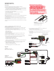
1) Install the Pickups and route the cables to the control cavity.
If the cables are too long, wind up the excess and keep it under the pickup.
2) Mount the Volume and Tone controls into the body
Plug both Neck and Bridge pickup cables onto the Volume Controls as shown.
Plug a coax cable from the Bridge (BR) Volume control to the Pickup Buss
(Position 1). See Diagram #7
Plug a coax cable from the Neck (NK) Volume control to the Pickup Buss
(Position 2). See Diagram #7
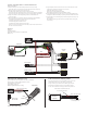
3) Plug a coax cable from the Bridge (BR) Volume control to the Bridge (BR) Tone
control as shown.
4) Plug a coax cable from the Neck (NK) Volume control to the Neck (NK) Tone
control as shown.
5) Strip the insulation from the switch wires and Insert them into the GREEN
Terminal Block and tighten the screws with a small screwdriver.
The Bridge pickup goes to the BR Terminal
The Neck Pickup goes to the NK Terminal
The Output of the switch goes to the O Terminal
If there is a ground wire coming from the switch, insert it into one of the black
terminals on the terminal block.
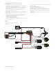
6) Plug the output cable onto the Pickup Buss (Position 3) and push the connectors
onto the jack as shown.
WHITE wire onto the TIP (T) contact,
BLACK wire onto the SLEEVE (S) contact
BLACK Battery Negative wire onto the RING (R) contact.
7) Plug the RED Wires of the pickups onto the V+ Supply Buss (RED Shroud)
along with the RED of the battery clip. Extra pins are for EMG Accessories.
8) Put the battery in the foam insulator provided and place it securely in the
control cavity.
We suggest that you plug in the instrument and test it before closing the
control cavity.
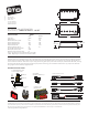
Diagram #5
2 Pickups
2 Volume (either volume will act as a master)
2 Tone
Toggle Style Switch
2 Pickups / Toggle Select Switch / 2 Volumes and 2 Tones)
Refer to Diagram #5
T
R
S
NK VOLUME
FROM NECK PICKUP
FROM BRIDGE PICKUP
BR VOLUME
BATTERY
NEG (-)
NK TONE
BR TONE
OUTPUT CABLE
- 9V +
GROUND
BRIDGE P/U
NECK P/U
OUTPUT