
CAST IRON DIRECT VENT FIREPLACE INSTALLATION INSTRUCTIONS AND OWNER'S MANUAL MODEL CIDV-30-7

Page 10 R-5086
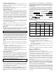
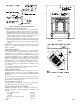
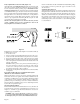
Delayed Ignition Reset Switch Assembly (Figure 14)
Attach black wire from REMOTE/OFF/ON switch to the front 1/4" male
tab on the reset switch. Attachment of black wire onto the reset switch is
done in conjunction with the preceding steps for Installation of Wire
Channel Assembly. Black wire on the back of the reset switch is attached
to the TH/TP terminal on gas valve (this connection is factory installed).
The reset switch can be activated if the main burner has a delayed ignition.
The right, relief door is connected by a metal wire to a cotter pin that is
inserted into the reset switch. When a delayed ignition occurs the right,
relief door pivots upward, the metal wire pulls the cotter pin out of the
reset switch and the main burner is shut OFF.
Whenever the delayed ignition reset switch is activated you must
contact a qualified service person to determine the cause for the
delayed ignition reset switch to be activated.
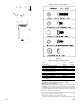
Figure 14
Replacement of cotter pin into delayed ignition reset switch assembly by
a qualified service person.
1. Lower valve cover.
2. The reset switch is located behind the right side of the valve cover.
3. Verify the metal cable with attached cotter pin has free movement.
4. Depress the metal lever arm located on the front of the reset switch.
5. With the metal lever arm depressed, insert cotter pin into the clearance
hole on the right side of the bracket and into the clearance hole on the
left side of the bracket.
Attention: The tip of the cotter pin must remain flat. The tip of
the cotter pin must never be bent-over. If the tip of the cotter pin
is bent-over it could prevent the delayed ignition reset switch
from functioning during a delayed ignition.
6. Replacement of cotter pin into delayed ignition reset switch assembly
is completed.
Reassembly and Resealing Gas Accumulation Relief System
(Relief Doors) and Combustion Chamber
Whenever the relief doors are pivoted open by a delayed ignition in the
main burner, the relief door gaskets and combustion chamber must be
examined by a qualified service person for damage. All damaged gaskets
on the relief doors and combustion chamber must be replaced by a
qualified service person. If damage occurs to the combustion chamber, it
must be replaced by a qualified service person. Contact Empire Comfort
Systems, Inc. for replacement parts.
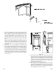
Sidewall Venting Installation
The maximum vertical and horizontal distances for one (1) 90° elbow are
25 feet and 12 feet, respectively. Vertical dimensions are based on top of
fireplace to centerline of pipe. Horizontal dimensions are based on
centerline of pipe to termination.
CAUTION: Total vertical run MUST BE completed before starting
horizontal run. Horizontal chimney run must slope upward (away
from fireplace)1/4" per foot and vent termination must be level.
Under no circumstances should combustible materials (including siding)
be closer than 2" from the top of the 6 5/8" pipe or closer than 1" on the
side and bottom.
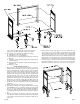
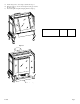
Cutting the Hole (Figure 15)
After the appliance has been positioned in its permanent location, the hole
through the exterior wall of the house can be cut. This hole needs to be 10"
high x 10" wide square with its center line determined by the amount of
vertical arise and horizontal run of the termination. When locating the
hole it must be noted that the bottom of the cap must be 12" above the
ground level, and top of the cap must be no less than 18" below a
combustible projection, and no closer than 9" to any wall running parallel
to vent termination.