
CAST IRON DIRECT VENT FIREPLACE INSTALLATION INSTRUCTIONS AND OWNER'S MANUAL MODEL CIDV-30-7

Page 6 R-5086
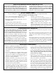
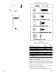
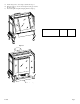
Appliance Hardware Package (Figure 6)
Figure 6
Appliance Hardware Package Parts List
Part Part Quantity
Description Number Supplied
1/4-20 x 1" Phillips Head Bolt R-3188 4
1/4-20 x 3/8" Phillips Head Bolt R-3646 16
1/4-20 x 1/2" Leveling Bolt R-3747 4
No. 10 x 1/2" R-2737 8
Hex Washer Head Screw
1/4-20 Washer Head Nut R-3185 4
Leg Pad "A" (see Figure 7) CI-008 2
Leg Pad "B" (see Figure 7) CI-009 2
1-1/4" x 1/2" Retaining Tab CI-007 4
(see Figure 10)
1/4 x 9/32 Washer (Not Shown) R-1150 8
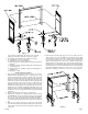
Assembly of Cast Iron (Outer Casing) Stove Casting
(Figures 7, 8, 9, 10, 11 and 12)
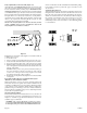
Attention: Included in the hardware package are (8) 1/4" inside diam-
eter washers. A 1/4" washer may be used with a 1/4-20 x 3/8" bolt when
assembling the stove casting parts. If a bolt hole is not tapped deep
enough for a tight fit between stove casting parts, the 1/4" washer can
be used as a shim to provide a tight fit.
The 1/4" washers are not required for assembly of the stove casting if all
the bolt holes are tapped to a proper depth.
Additonal 1/4" washers are to be purchased locally.
1. Place porcelain casting pieces on a non-abrasive surface in order