INSTALLATION INSTRUCTIONS AND OWNER'S MANUAL FAN TYPE VENTED WALL FURNACE MODEL FAW-40-1SPP FAW-40-1IP EFFECTIVE DATE SEPTEMBER 2003 WARNING: If the information in this manual is not followed exactly, a fire or explosion may result causing property damage, personal injury or loss of life. — Do not store or use gasoline or other flammable vapors and liquids in the vicinity of this or any other appliance. Installer: Please leave these instructions with the consumer.
Introduction Always consult your local Building Department regarding regulations, codes or ordinances which apply to the installation of a vented wall furnace. Instructions to Installer 1. Installer must leave instruction manual with owner after installation. 2. Installer must have owner fill out and mail warranty card supplied with furnace. 3. Installer should show owner how to start and operate furnace and thermostat. Warning: Any change to this furnace or its control can be dangerous.
SAFETY INFORMATION FOR USERS OF LP-GAS Propane (LP-Gas) is a flammable gas which can cause fires and explosions. In its natural state, propane is odorless and colorless. You may not know all the following safety precautions which can protect both you and your family from an accident. Read them carefully now, then review them point by point with the members of your household. Someday when there may not be a minute to lose, everyone's safety will depend on knowing exactly what to do.
Ventilation and Combustion Air WARNING: Danger of property damage, bodily injury or death, this furnace and any other fuel burning appliance must be provided with enough fresh air for proper combustion and ventilation of flue gases. Most homes will require that outside air be supplied. Do not draw air from a corrosive environment such as a workshop or laundry room. The requirements for providing air for combustion and ventilation are listed in the National Fuel Gas Codes NFPA 54/ANSI Z223.
Qualified Installing Agency Installation and replacement of gas piping, gas utilization equipment or accessories and repair and servicing of equipment shall be performed only by a qualified agency.
Page 6 12427-2-0903
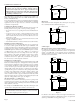
8. Align clearance holes on 6" x 10" (152mm x 254mm) duct with screw holes on inner casing back and mark duct to be 2 1/4" (57mm) shorter than 8" x 12" (203mm x 305mm) boot. Remove duct and cut to proper length. 9. Attach 6" x 10" (152mm x 254mm) duct to inner casing back with (4) #8 x 3/8" (9mm)screws removed in Step 3, 2 on top and 2 on bottom. 10. Insert rear register into 8" x 12" (203mm x 305mm) boot. Attach rear register to wall with (2) #10 x 1"(25mm) screws provided. 11.
Attention! If one of the above procedures results in pressures in excess of 1/2 psig (14" w.c.) (3.5 kPa) on the appliance gas valve, it will result in a hazardous condition. Checking Manifold Pressure Both Propane and Natural gas valves have a built-in pressure regulator in the gas valve. Natural gas models will have a manifold pressure of approximately 4.0" w.c. (.996kPa) at the valve outlet with the inlet pressure to the valve from a minimum of 5.0" w.c. (1.
Oiling the Motor The fan motor should be cleaned and oiled once each heating season. Oil holes are located on the top at each end of the motor. Use a few drops of #10 motor oil. To clean the motor, blow air through its ventilation openings with a vacuum cleaner or low pressure air source. Wiring The appliance, when installed, must be electrically grounded in accordance with local codes or, in the absence of local codes, with the National Electrical Code, ANSI/NFPA 70 or Canadian Electrical Code, CSA C22.
To adjust: 1. Remove the pilot adjustment cover screw. 2. Turn the inner adjustment screw clockwise to decrease to increase pilot flame. Pilot adjustor counterclockwise ment is shipped at full flow rate. Turn the inner adjustment screw clockwise if the inlet pressure is too high. 3. Replace the cover screw after the adjustment to prevent gas leakage. PRESSURE REGULATOR ADJUSTMENT-UNDER CAP SCREW OUTLET PRESSURE TAP CAUTION: Label all wires prior to disconnection when servicing controls.
STANDING PILOT MODEL FOR YOUR SAFETY READ BEFORE LIGHTING WARNING: If you do not follow these instructions exactly, a fire or explosion may result causing property damage, personal injury or loss of life. A. This appliance has a pilot which must be lighted by hand. When lighting the pilot, follow these instructions exactly. B. BEFORE LIGHTING smell all around the appliance area for gas. Be sure to smell next to the floor because some gas is heavier than air and will settle on the floor.
INTERMITTENT PILOT (IP) MODEL FOR YOUR SAFETY READ BEFORE OPERATING WARNING: If you do not follow these instructions exactly, a fire or explosion may result causing property damage, personal injury or loss of life. A. This appliance is equipped with an ignition device which automatically lights the pilot. Do not try to light the pilot by hand. B. BEFORE OPERATING smell all around the appliance area for gas.
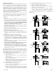
SEQUENCE OF OPERATION Apply 24 VAC to Appliance START Thermostat Calls for Heat 5 Minute Retry Delay Flame Signal Detected YES • Pilot Valve Ignition OFF • Wait for Flame Signal to Disappear System Check NO Internal Check OK NO YES Trial for Ignition • Pilot Valve Opens • Ignitor Powered Pilot Light and Flame is Sensed During Trial For Ignition (1) NO • Pilot Valve Closes • Ignition OFF 3 Second Flame Failure Recycle Delay YES Main Burner Operation • Ignitor OFF • Main Valve Opens YES Flame Sig
IP SYSTEM TROUBLESHOOTING SEQUENCE START SmartValve™ System Troubleshooting Sequence Note: Before Troubleshooting, Become Familiar with the Sequence of Operation • Turn OFF Gas Supply • Disconnect System Control Harness • Set Thermostat to Call for Heat Check for Proper Voltage at Control Harness (See Inset A -Voltage Should be 24V Between Thermostat and 24V Common, and 24V Between 24V Common and 24V Hot.
PLEASE NOTE: When ordering parts, it is very important that part number and description of part coincide. INDEX NO.
Page 16 12427-2-0903
Service Notes 12427-2-0903 Page 17
Empire Comfort Systems, Inc. Nine Eighteen Freeburg Ave. Belleville, Illinois 62220-2623 Page 18 PH: 1-618-233-7420 PH: 1-800-851-3153 FAX: 1-618-233-7097 FAX: 1-800-443-8648 E-MAIL: info@empirecomfort.com WEB SITE: www.empirecomfort.
INSTRUCTIONS POUR L’INSTALLATION ET MANUEL DU PROPRIÉTAIRE RADIATEUR MURAL À CIRCULATION FORCÉE ET AVEC ÉVACUATION MODÈLE FAW-40-1SPP FAW-40-1IP DATE D’ENTRÉE EN VIGUEUR SEPTEMBRE 2003 AVERTISSEMENT: Si les informations dans ce manuel ne sont pas exactement suivies, un feu ou une explosion peut en résulter causant des dommages à la propriété, des blessures corporelles ou la mort. Installateur: S'il vous plaît, laissez ces instructions avec le consommateur.
Introduction Toujours consulter le département de construction de votre région en ce qui regarde les règlements, les codes ou les ordonnances qui s’appliquent à l’installation d’un radiateur mural avec évacuation. Instructions pour l'Installateur 1. Après l’installation, l’installateur doit laisser le manuel d’instructions au propriétaire. 2. L’installateur doit demander au propriétaire de compléter et poster la carte de guarantie de l’unité de chauffage. 3.
INFORMATION DE SÉCURITÉ POUR LES UTILISATEURS DE PROPANE Le propane est un gaz inflammable qui peut causer des feux et des explosions. Dans son état naturel, le propane est inodore et sans couleur. Peut-être que vous ne connaissez pas toutes les précautions décrites ci-dessous? Elles peuvent vous protéger ainsi que votre famille contre un accident. Lisez-les attentivement dès maintenant, puis réexaminez les, point par point avec les membres de votre famille.
Air de Ventilation et de Combustion ATTENTION: Danger pour des dommages à la propriété, des blessures ou la mort, ce radiateur et d’autre sorte d’appareil au gaz doivent avoir assez d’air frais pour permettre une bonne combustion et une bonne ventilation des gaz d’échappement. La plupart des maisons exigera que l’air extérieur soit accessible. Ne tirez pas de l’air venant d’un environnement malsain comme un atelier ou une chambre à lavage.
ROND 4" Si l’air de combustion est pris à l’extérieur par des conduits horizontaux, les ouvertures et les conduits doivent avoir un espace libre minimum de 1"2 (6.5cm2) par 2,000 Btuh d’entrée totale pour l’appareil. Agence d’Installation Qualifiée L’installation et le remplacement des tuyaux à gaz, des équipements ou accessoires, la réparation et l’entretien de l’équipement doivent être faits seulement par une agence qualifiée.
4. Les évents à gaz de type B-1 ou (B-W) pour plus d’un étage exige une plaque de base, une paire d’entretoises pour la plaque du plafond, au plafond du premier étage et une paire d’entretoises pour l’arrêt de feu à chaque niveau de plafond successif. L’espace entre les montants autour des évents à gaz doit être sans obstruction et sans papier de construction Pour installer le SOK-1, s’il vous plaît utilisé les étapes 1 jusqu’à 5 dans les instructions du SOR-1 pour les radiateurs FAW-40.
arrière pour former un carré. Percer un trou pilote à l’intérieur du carré que vous avez tracé sur la paroi extérieure arrière. Enlever la feuille de métal à l’intérieur du carré que vous avez tracé, avec des ciseaux à métal ou un outil comparable. 3. Enlever les (4) vis # 8 x 3/8" (9mm) qui attachent la plaque de fermeture de la paroi intérieure, à la paroi intérieure. 4. Insérer l’écran protecteur à travers la paroi extérieure arrière et l’arrière de la paroi intérieure.
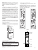
TUYAU D’ALIMENTATION EN GAZ BONDE NPT DE 1/8 POUR VÉRIFIER LE JAUGEAGE DES CONNEXIONS. VALVE À GAZ VALVE VUE DE DESSUS ÉVENT RÉGULATEUR DE PRESSION CONNECTEUR TH/TR PRISE POUR SORTIE DE PRESSION VALVE DE FERMETURE MANUELLE ENTRÉE DE GAZ SORTIE DE GAZ RACCORD HORIZONTAL PRISE POUR PRESSION D’ENTRÉE ARRIVÉE D’ALIMENTATION DE GAZ BONDE NPT DE 1/8 POUR VÉRIFIER LE JAUGEAGE DES CONNEXIONS. BOUTON ROUGE DE REMISE À ZÉRO 3" (7.
Le gaz propane n’exige aucun ajustement. Après l’usage, un nettoyage peut être exigé pour obtenir une flamme convenable. Aspect Convenable de la Flamme du Brûleur Principal La flamme convenable aura une petite flamme bleue intérieure avec une flamme extérieure bleue pâle beaucoup plus grande. Il n’y a pas d’ajustement d’air primaire pour le brûleur. La flamme se corrigera si la pression pré-ajustée à l’usine et les ouvertures sont utilisées.
Figure 13 CONNECTEUR DU TUYAU FLUE CONNECTOR D’ÉVACUATION INTERRUPTEUR DE FIN DE VENT LIMIT SWITCH COURSE POUR L’ÉVENT DRAFT DIVERTER COUPE-TIRAGE FAN VENTILATEUR INTERRUPTEUR DU LIMIT SWITCH VENTILATEUR FAN SWITCH FAN SWITCH BURNER BOÎTE DUBOX BRÛLEUR PIEZO SUGGESTIONS POUR LE SERVICE ET L’ENTRETIEN. Appeler un technicien d’entretien. Général : Tous les radiateurs ont reçu un test d’allumage pour vérifier le bon fonctionnement.
Veilleuse modèle IP Ce radiateur utilise un système “Smart Valve” Honeywell pour l’allumage intermittent de la veilleuse. Lors d’un appel de chaleur par le thermostat, cette commande fera fonctionner la mini surface chaude d’allumage laquelle allumera la veilleuse qui elle à son tour allumera le brûleur principal.
MODÈLE DE LA VEILLEUSE FIXE POUR VOTRE SÉCURITÉ LIRE AVANT D’ALLUMER AVERTISSEMENT: Si vous ne suivez pas exactement ces instructions, un feu ou une explosion peut se produire causant des dommages à la propriété, des blessures corporelles ou la mort. A. Cet appareil a une veilleuse qui doit être allumée manuellement. Lorsque vous allumez la veilleuse, suivez exactement ces instructions. B. AVANT D’ALLUMER, sentez partout dans l’appartement dans lequel l’appareil est situé pour déceler une odeur de gaz.
MODÈLE DE LA VEILLEUSE INTERMITTENTE (IP) POUR VOTRE SÉCURITÉ LIRE AVANT D’ALLUMER AVERTISSEMENT: Si vous ne suivez pas exactement ces instructions, un feu ou une explosion peut se produire causant des dommages à la propriété, des blessures corporelles ou la mort. A. Cet appareil est muni d'un dispositif d'allumage lequel allume automatiquement la veilleuse. Ne pas essayer d'allumer la veilleuse manuellement. les instructions du fournisseur de gaz.
Séquence de Fonctionnement Appliquer 24 VAC à l'appareil Départ Thermostat Effectue un Appel de Chaleur Délai de 5 minutes, Essai de Nouveau Signal de la Flamme est Détecté OUI • Allumage de la Soupape de la Veilleuse FERMER • Attendre que le Signal de la Flamme Disparaisse Vérification du Système NON Vérification Interne OK NON OUI Essai d'Allumage • Soupage de la Veilleuse s'ouvre • Allumeur est mis en Fonction La Lumière et la Flamme de la Veilleuse sont Discernées Pendant l'Essai d'Allumage (1)
Guide de Détection des Défectosités pour le Système IP Départ Guide de détection des défectuosités pour le système "Smart Valve" Note: Avant que les défectuosités apparaissent, familiarisez-vous avec les séquences de defonctionnement.
PLEASE NOTE: When ordering parts, it is very important that part number and description of part coincide. Index No.
12427(F)-2-0903 Page 17
Empire Comfort Systems, Inc. Nine Eighteen Freeburg Ave. Belleville, Illinois 62220-2623 Page 18 PH: 1-618-233-7420 PH: 1-800-851-3153 FAX: 1-618-233-7097 FAX: 1-800-443-8648 E-MAIL: info@empirecomfort.com WEB SITE: www.empirecomfort.