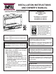
EMPIRE Comfort Systems INSTALLATION INSTRUCTIONS AND OWNER'S MANUAL Loft Vent Free Fireplace/Insert unVented GAS Fireplace ModELS VFL20IN3(0,1,2,3)10(N,P)-1 VFL20IN3(0,1,2,3)(N,P)-1 VFL20IN7(0,1,2,3)(N,P)-1 GAS-FIRED Shown without required front. Installer: Leave this manual with the appliance. Consumer: Retain this manual for future reference.
TABLE OF CONTENTS SECTION PAGE Important Safety Information........................................................................................................... 3 Safety Information for Users of LP-Gas.......................................................................................... 4 Important Installation Guidelines..................................................................................................... 5 Introduction.............................................................
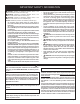
IMPORTANT SAFETY INFORMATION DANGER: Indicates a hazardous situation which, if not avoided, will result in death or serious injury. WARNING: Indicates a hazardous situation which, if not avoided, could result in death or serious injury. CAUTION: Indicates a hazardous situation which, if not avoided, could result in minor or moderate injury. NOTICE: Addresses practices not related to personal injury.
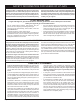
SAFETY INFORMATION FOR USERS OF LP-GAS Propane (LP-Gas) is a flammable gas which can cause fires and explosions. In its natural state, propane is odorless and colorless. You may not know all the following safety precautions which can protect both you and your family from an accident. Read them carefully now, then review them point by point with the members of your household. Someday when there may not be a minute to lose, everyone's safety will depend on knowing exactly what to do.
IMPORTANT INSTALLATION GUIDELINES Proper Primary Airflow into Burner For proper burner operation and flame appearance, the flow of primary air into the venturi tube, located on the rear of the burner, must not be reduced. This flow of air is reduced if dirt, lint or other obstructions build-up around or inside the venturi. Any obstruction in the venturi tube area must be removed.
INTRODUCTION Instructions to Installer 1. Installer must leave instruction manual with owner after installation. 2. Installer must have owner fill out and mail warranty card supplied with unvented room heater. 3. Installer should show owner how to start and operate unvented room heater. Always consult your local Building Department regarding regulations, codes or ordinances which apply to the installation of an unvented room heater.
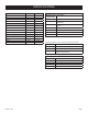
SPECIFICATIONS VFL20IN3* LP NAT Input Btu/hr Maximum 20,000 20,000 Btu/hr Minimum 16,000 13,000 #55 2.
INSTALLATION IN A FIREPLACE 1. Before beginning, check to make sure there is no hidden damage to the unit. Take a minute and plan out the gas and electrical route. It is best to start with the gas line first, followed by the electrical supply requirements. 2. Minimum fireplace opening requirements are shown in Figure 2 of this installation manual.
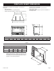
FIREPLACE INSERT DIMENSIONS When planning a fireplace insert installation, it’s necessary to determine: • Gas supply piping. • Electrical connections - for optional blower • Whether optional accessories - devices such as a wall switch or remote control - are desired. Electrical supply requirements for optional blower. (120V, 60Hz, 1 Amp) Proper opening size of fireplace required for installation of the fireplace insert.
BUILT-IN FIREPLACE INSTALLATION In planning the installation for the fireplace, it is necessary to determine where the unit is to be installed and whether optional accessories are desired. Gas supply piping should also be planned at this time. on a metal or wood panel extending the full width and depth of the unit. At this point, you should have decided what components to include in your installation, and where the fireplace is to be located.
FIREPLACE WITH SURROUND DIMENSIONS 34” 11 1/2” 20 1/2” 25” 4 19/64” DF20GBL 39 15/16” 25 1/2” 1 3/4” DF20LBL 37 3/8” 23 13/32” 2 1/4” DF20MBL 27407-4-1010 Page 11
WATER VAPOR: A BY-PRODUCT OF UNVENTED ROOM HEATERS Water vapor is a by-product of gas combustion. An unvented room heater produces approximately one (1) ounce (30ml) of water for every 1,000 BTU's (.3KW's) of gas input per hour. Unvented room heaters are recommended as supplemental heat (a room) rather than a primary heat source (an entire house). In most supplemental heat applications, the water vapor does not create a problem.
PROVISIONS FOR ADEQUATE COMBUSTION & VENTILATION AIR (continued) The space in the above example is a confined space because the actual BTU/Hr used is more than the maximum BTU/HR the space can support. You must provide additional fresh air. Your options are as follows: A. Rework worksheet, adding the space of an adjoining room. If the extra space provides an unconfined space, remove door to adjoining room or add ventilation grills between rooms. See Ventilation Air From Inside Building. B.
GAS SUPPLY The gas pipeline can be brought in through the right or left side of the appliance. The insert has a Flexline with shutoff valve located on the right side when facing the unit. See Figures 8 and 9. Consult the current National Fuel Gas Code, ANSI Z223.1 CAN/CGA-B149 (.1 or .2) installation code. Recommended Gas Pipe Diameter Pipe Length Schedule 40 Pipe Inside Diameter Tubing, Type L Outside Diameter Nat. L.P. Nat. L.P. 0-10ft 0-3m 1/2" 12.7mm 3/8" 9.5mm 1/2" 12.7mm 3/8" 9.
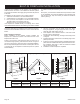
GAS SUPPLY (continued) Checking Manifold Pressure MILLIVOLT VALVES Natural gas will have a manifold pressure of approximately 3.5" w.c. for maximum input or 1.7" w.c. for minimum input at the pressure regulator outlet with the inlet pressure to the pressure regulator from a minimum of 4.5" w.c. for the purpose of input adjustment to a maximum of 10.5" w.c. Propane gas will have a manifold pressure approximately 10.0"w.c. (2.49kPa) for maximum input or 4.9"w.c.
COMBUSTIBLE MATERIALS Combustible Material No greeting cards, stockings or ornamentation of any type should be placed on or attached to the fireplace. The flow of heat can ignite combustibles. Do not attach combustible material to the mantel of your fireplace. This is a fire hazard. No greeting cards, stockings or ornamentation of any type should be placed on or attached to the fireplace. This is a heating appliance. The flow of heat can ignite combustibles.
ALTERNATE ON/OFF SWITCH INSTALLATION WIRING THE FIREPLACE 6. WARNING Electrical wiring must be installed by a licensed electrician. WARNING DISCONNECT REMOTE CONTROLS IF YOU ARE ABSENT FOR EXTENDED TIME PERIODS. THIS WILL PREVENT ACCIDENTAL FIREPLACE OPERATION. Installation of Alternate Surround Panel ON/OFF Switch on the millivolt control valve only. An ON/OFF switch and wire assembly are provided. They are included in the instruction packet. Do not cut wire or insulation on metal edges.
DECORATIVE ACCESSORY INSTALLATION WARNING DECORATIVE GLASS Failure to position the parts in accordance with the diagrams and instructions below or failure to use only parts specifically approved for use with this heater may result in property damage or personal injury. Notice: The Loft series burners may be operated with or without the Decorative accessory options. Follow the directions below should you choose to enhance your Loft burner with any one of the available decorative options.
MILLIVOLT CONTROL VALVE LIGHTING INSTRUCTIONS FOR YOUR SAFETY READ BEFORE LIGHTING Warning: If you do not follow these instructions exactly, a fire or explosion may result causing property damage, personal injury or loss of life. A. B. This appliance has a pilot which must be lighted by hand. When lighting the pilot, follow these instructions exactly. department. C. Use only your hand to push in or turn the gas control knob. Never use tools.
10,000 BTU MILLIVOLT CONTROL VALVE LIGHTING INSTRUCTIONS FOR YOUR SAFETY READ BEFORE LIGHTING Warning: If you do not follow these instructions exactly, a fire or explosion may result causing property damage, personal injury or loss of life. A. B. This appliance has a pilot which must be lighted by hand. When lighting the pilot, follow these instructions exactly. department. C. Use only your hand to push in or turn the gas control knob. Never use tools.
INTERMITTENT PILOT LIGHTING INSTRUCTIONS FOR YOUR SAFETY READ BEFORE LIGHTING Warning: If you do not follow these instructions exactly, a fire or explosion may result causing property damage, personal injury or loss of life. A. BEFORE LIGHTING, smell all around the appliance area for gas. Be sure to smell next to the floor because some gas is heavier than air and will settle on the floor.
INTERMITTENT PILOT OPERATING INSTRUCTIONS Thermostats are not approved on vented decorative appliances. Label all wires prior to disconnection when servicing controls. Wiring errors can cause improper and dangerous operation. Verify proper operation after servicing. The 7 series Loft Fireplace operate with a GV60 battery-powered electronic remote ignition and control system.
INTERMITTENT PILOT REMOTE ELECTRONIC IGNITION AND CONTROL SYSTEM APPLICATION GV60 is a battery-powered electronic and control system for gas appliances with pilot burners and ODS systems. Timer/Thermostat RF Remote Handset G6R-H3T GENERAL NOTES Radio Frequency Remote 433.92 MHz for Europe; 315 MHz for U.S. (FCC ID: RTDG6R) and for Canada (IC: 4943A-G6R). This device complies with part 15 of the FCC Rules.
INTERMITTENT PILOT REMOTE ELECTRONIC IGNITION AND CONTROL SYSTEM AUTOMATIC OPERATION WARNING Wiring of valve and receiver must be completed before starting ignition. Failure to do so could damage the electronics. SETTING THE ELECTRONICS CODE Notice: The remote control and receiver are pre-programmed at the factory. However, if for some reason they do not communicate to each other, follow these steps to re-program. • Continuing beeps confirm the ignition is in process.
INTERMITTENT PILOT REMOTE ELECTRONIC IGNITION AND CONTROL SYSTEM SETTING THE TIME Display, Timer/Thermostat RF Remote Handsets Notice: The display shows the set temperature every 30 seconds. • SETTING THE TEMPERATURE TEMP • Select either the TEMP MODE or the MODE by briefly pressing the SET button. • Hold the SET button until the TEMP display flashes. The display will flash after either: a. Installing the battery or b.
INTERMITTENT PILOT REMOTE ELECTRONIC IGNITION AND CONTROL SYSTEM 7. With the MANUAL knob in MAN position a manual pilot valve operator and piezo igniter are accessible. Ignition with match: Fully push down manual pilot valve operator and hold in, to start pilot gas flow. Immediately light the pilot with a match, while continuing to hold in the manual pilot valve operator for about one (1) minute after the pilot is lit. Release manual pilot valve operator.
INTERMITTENT PILOT WIRING DIAGRAM Main Valve Knob Manual Knob Piezo Igniter Connection for manual ignition Combination Control ON/OFF Switch Interrupter Block O 8 Wire Cable I Thermo Current Cable #2 or ON/OFF Switch with Soldered Cable Thermo Current Cable #1 Thermocouple Ignition Cable RF Antenna SPARK SW TC MA GR MO PANEL SW Battery Compartment Button “RESET” 27407-4-1010 Page 27
OPERATION INSTRUCTIONS/FLAME APPEARANCE Flames from the pilot (front center of burner) as well as the main flame should be visually checked as the fireplace is installed. In normal operation at full rate after 10 to 15 minutes, the flame appearance should be sets of yellow flames. Notice: All flames will be random by design, flame height will go up and down. Avoid any drafts that alter burner flame patterns. Do not allow fans to blow directly into fireplace.
PILOT FLAME CHARACTERISTICS Figures 25 and 26 show a correct pilot flame pattern. The correct flame will be blue and will extend beyond the thermocouple. The flame will surround the thermocouple just below the tip. A slight yellow flame may occur where the pilot flame and main burner flame meet. Figures 27 and 28 show an incorrect pilot flame pattern. The incorrect pilot flame is not touching the thermocouple. This will cause the thermocouple to cool. When the thermocouple cools, the heater will shut down.
PILOT FLAME CHARACTERISTICS Cleaning and Maintenance/Pilot Oxygen Depletion Sensor Pilot (Figures 29 and 30) When the pilot has a large yellow tip flame, clean the Oxygen Depletion Sensor as follows: 1. Clean the ODS pilot by loosening nut B from the pilot tubing. When this procedure is required, grasp nut A with an open end wrench. 2. Blow air pressure through the holes indicated by the arrows. This will blow out foreign materials such as dust, lint and spider webs. Tighten nut B also by grasping nut A.
WIRING Label all wires prior to disconnection when servicing controls. Wiring errors can cause improper and dangerous operation. Verify proper operation after servicing. WIRING DIAGRAM (OPTIONAL) WALL SWITCH INTERRUPTEUR MURAL (FACULTATIVE) Use the two leads (Red and Green) to attach optional components. Refer to remote control installation and operating instructions for more details on remote control.
TROUBLESHOOTING SYMPTOMS, POSSIBLE CAUSES AND CORRECTIONS 1. When ignitor button is pressed, there is no spark at ODS/ pilot. a. Ignitor electrode positioned wrong - Replace pilot. b. Ignitor electrode is broken - Replace pilot. c. Ignitor electrode not connected to ignitor cable - Reconnect ignitor cable. d. Ignitor cable pinched or wet. Keep ignitor cable dry - Free ignitor cable if pinched by any metal or tubing. e. Broken ignitor cable - Replace ignitor cable. f.
PARTS LIST Index No. Part No. 1 27547 Description COMMON PARTS Index No. Part No.
EXPLODED VIEW 1 22 23 10 5 7 6 9 8 25 24 4 3 2 11 13 12 15 16 12 13 14 26 TEMP SET 17 14 15 16 PM OFF 18 19 21 17 18 20 MILIVOLT VALVE ASSEMBLY Page 34 19 IPI VALVE ASSEMBLY 27407-5-1010
SURROUND FRONTS This fireplace requires a surround, available from your Empire Comfort Systems dealer. The DF20LBL surround shown below allows the fireplace to be installed as an insert in an existing fireplace or in a mantel. For elevated installation in a wall, see the DF20GBL and DF20MBL surrounds on the following page. If you need additional information beyond what your dealer can furnish, contact Empire Comfort Systems Inc., Nine Eighteen Freeburg Ave., Belleville, Illinois 62220.
SURROUND FRONTS The fireplace requires a surround, available from your Empire Comfort Systems dealer. The DF20GBL and DF20MBL surrounds shown below allow the fireplace to be installed elevated in a wall. For installation as an insert in an existing fireplace or in a mantel, see the DF20LBL on the previous page. DF20GBL Glass Front 34" x 20 1/2" glass panel with mounting brackets, shield and hardware.
MASTER PARTS DISTRIBUTOR LIST To Order Parts Under Warranty, please contact your local Empire dealer. See the dealer locator at www.empirecomfort.com. To provide warranty service, your dealer will need your name and address, purchase date and serial number, and the nature of the problem with the unit. To Order Parts After the Warranty Period, please contact your dealer or one of the Master Parts Distributors listed below. This list changes from time to time.
APPLIANCE SERVICE HISTORY Date Page 38 Dealer Name Service Technician Name Service Performed/Notes 27407-5-1010
APPLIANCE SERVICE HISTORY Date Dealer Name 27407-4-1010 Service Technician Name Service Performed/Notes Page 39
EMPIRE Comfort Systems Empire Comfort Systems Inc. 918 Freeburg Ave. Belleville, IL 62220 If you have a general question about our products, please e-mail us at info@empirecomfort.com. If you have a service or repair question, please contact your dealer. www.empirecomfort.