
Owner`s manual

27407-5-1010Page 10
In planning the installation for the replace, it is necessary to
determine where the unit is to be installed and whether optional
accessories are desired. Gas supply piping should also be planned
at this time.
The replace can be mounted on any of these surfaces:
1. A at hard combustible or non-combustible surface.
2. A raised platform of combustible or non-combustible material.
3. Four (4) corners of the replace so contact is made on all four
perimeter edges on the bottom of the unit.
(Example: Four (4) concrete masonry blocks.)
If the fireplace is installed directly on carpeting, tile or other
combustible material other than wood ooring, it should be installed
on a metal or wood panel extending the full width and depth of the
unit.
At this point, you should have decided what components to include
in your installation, and where the replace is to be located. If this
has not been done, stop and consult your dealer for assistance
with this planning.
BUILT-IN FIREPLACE INSTALLATION
This unit is designed to be installed in a zero-clearance enclosure.
This means the combustible material can come in contact with the
rebox.
Built-In Fireplace Installation
Built-in installation of this replace involves installing the
replace into a framed-in enclosure. This makes the front of the
replace ush with a wall.
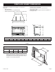
Frame in rough opening. Use dimensions show in Figure 3 for a
conventional rough opening. Use dimensions shown in Figure 4
for corner rough opening. Use Figure 5 for an elevated installation.
Be sure to provided support to the bottom of the replace. Be sure
to provide gas line for replace and electrical power for optional
blower assembly.
1. Gas line connections must be made at this time. When
facing the appliance, the gas supply will enter on the right-
hand side. See "Gas Supply" page 14.
2. Insert replace into enclosure. Attach to wall with screws
through holes on cabinet sides.
3. Level rebox. See "Positioning, Leveling and Securing Insert"
on Page 8.
4. Finished wall surface will be ush to the leading edge of re-
place top and sides.
5. If used, the surround panel assembly is installed after the re-
place has been installed with all the gas and electrical connec-
tion completed. See Page 17. Refer to instructions included
with the surround panel kit.
6. Installation of built-in replace is completed.
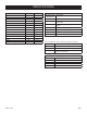
Rough Opening for Installing in Wall Rough Opening for Installing in Corner Rough Opening for Elevated Installation
FLUSH
INSTALLATION
PROJECTED
INSTALLATION
1” TO 6” FROM BACK
25mmTO 152mm
ELECTRICAL RECEPTACLE
71/2” (190.5mm)
GASSUPPLY
B
C
A
D
25 5/8”
650.9mm
E
51 1/4” (1301.8mm)
FLUSH
INSTALLATION
PROJECTED
INSTALLATION
1” TO 6” FROM BACK
25mmTO 152mm
ELECTRICAL RECEPTACLE
71/2” (190.5mm)
GASSUPPLY
B
C
A
6” MINIMUM
Figure 3 Figure 4 Figure 5
A B C D E
VFL20IN
13 3/4"
(349.3 mm)
27 3/4"
(704.9 mm)
19 1/4"
(489 mm)
36 1/4"
(920.8 mm)
27 3/4"
(704.9 mm)