
Owner`s manual

27407-5-1010Page 8
INSTALLATION IN A FIREPLACE
1. Before beginning, check to make sure there is no hidden dam-
age to the unit. Take a minute and plan out the gas and electri-
cal route. It is best to start with the gas line rst, followed by
the electrical supply requirements.
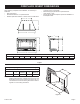
2. Minimum replace opening requirements are shown in
Figure 2 of this installation manual. The rebrick (refractory),
glass doors, screen rails, screen mesh and log grates can be
removed from a factory built replace in order to gain mini-
mum gas insert opening requirements prior to installing the
gas replace insert.
3. This insert requires no hearth extensions. Combustible ma-
terial on the oor may be installed up to the insert. Do not
obstruct the lower louver of the insert. The original replace
cannot be returned to solid fuel in this condition.
4. The metal oor of the solid fuel rebox may be removed to
facilitate the installation of the insert. The side walls and top
structure of the rebox may not be altered with the exception
of removable bafes and dampers. Smoke shields, shelves
and bafes may be removed if attached with mechanical fas-
teners. The original replace cannot be returned to solid fuel
in this condition.
5. The insert surround is tested and approved with this gas in-
sert and may cover existing air circulation vents or grills on the
solid fuel replace it is installed into. If the surround does not
cover the entire ventilation grill surface, the exposed grill area
should be left open.
Notice
Notice: The following statement is also provided on a sepa-
rate label plate in the instruction packet. Prior to installation
-
erence as required.
WARNING
only and cannot be used for burning wood or solid fuels un-
has been reapproved by the authority having jurisdiction.
See "Positioning, Leveling and Securing Insert" below.
6. Install the insert without the surround panels attached and
make all gas venting and electrical connections.
provided, an access hole of 1 1/2” diameter (37.5mm) or
less may be drilled through the lower sides or bottom of
access hole must be plugged with a non-combustible in-
sulation after the gas supply line has been installed.
7. The surround panel assembly is installed after the replace
has been installed with all the gas and electrical connections
completed. Refer to instructions included with the surround
panel kit.
Ensure there are no obstructions to side air passages of
decorative trim once installed on insert.
Positioning, Leveling and Securing Insert
1. Place the insert into position
Notice: The front anges of the insert (without surround panels)
should be set at approximately 1" in front of the face of
the replace.
2. Level the insert from side to side and front to back.
3. If necessary, use the leveling bolts included in the instruction
pack. Screw the legs into the nuts installed in the bottom of
the insert. Turn legs in until insert is level.
Notice: The best way to access the leveling bolt locations is
to remove the burner and rebox bottom.