
Owner`s manual


27407-4-1010 Page 9
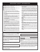
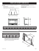
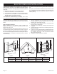
FIREPLACE INSERT DIMENSIONS
A
D
E
B
C
F
G
H
I
J
K
Figure 1
When planning a replace insert installation, it’s necessary to
determine:
• Gas supply piping.
• Electrical connections - for optional blower
• Whether optional accessories - devices such as a wall switch
or remote control - are desired.
• Electrical supply requirements for optional blower.
(120V, 60Hz, 1 Amp)
• Proper opening size of replace required for installation of
the replace insert.
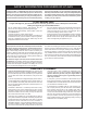
A
D
C
B
Figure 2
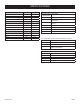
VF FIREPLACE INSERT DIMENSIONS
MODEL A B C D E F G H I J K
VFL20IN 29 1/4" 19 3/4" 12 7/16" 25 5/8" 16 3/16" 13 9/16" 25 3/4" 18 1/8" 15/16" 13 1/2" 1 5/8"
Fireplace Opening Dimensional Information/Sizing
MINIMUM FIREPLACE OPENING DIMENSIONS
MODEL HEIGHT
A
FRONT
WIDTH B
DEPTH
C
REAR
WIDTH D
VFL20IN 19 1/4" 26 1/2" 12 3/4" 15 3/4"
Notice: These are the minimum dimensions of a replace that the
replace insert will t into. It allows room for the box and
the replace surround to t onto the front of the unit. It is
not intended to be used for framing dimensions. Refer to
Figures 3 to 5 for framing dimensions.