EMPIRE Comfort Systems INSTALLATION INSTRUCTIONS AND OWNER'S MANUAL Cast Iron unVented room heater Models SMALL VFD(10,20)CC(30,70)(B,F,M)(N,P)-1 GAS-FIRED MEDIUM VFD30CC(30,70)(B,F,M,S,W)(N,P)-1 This appliance may be installed in an aftermarket, permanently located, manufactured (mobile) home, where not prohibited by local codes. This appliance is only for use with the type of gas indicated on the rating plate. This appliance is not convertible for use with other gases.
TABLE OF CONTENTS section page IMPORTANT SAFETY INFORMATION.............................................................................. 3 SAFETY INFORMATION FOR USERS OF LP-GAS.......................................................... 4 INTRODUCTION................................................................................................................ 5 SPECIFICATIONS..............................................................................................................
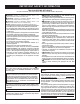
IMPORTANT SAFETY INFORMATION This Is a Heating Appliance Do Not Operate This Appliance Without Front Panel Installed. DANGER: Indicates a hazardous situation which, if not avoided, will result in death or serious injury. WARNING: Indicates a hazardous situation which, if not avoided, could result in death or serious injury. CAUTION: Indicates a hazardous situation which, if not avoided, could result in minor or moderate injury. NOTICE: Addresses practices not related to personal injury.
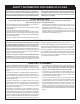
SAFETY INFORMATION FOR USERS OF LP-GAS Propane (LP-Gas) is a flammable gas which can cause fires and explosions. In its natural state, propane is odorless and colorless. You may not know all the following safety precautions which can protect both you and your family from an accident. Read them carefully now, then review them point by point with the members of your household. Someday when there may not be a minute to lose, everyone's safety will depend on knowing exactly what to do.
INTRODUCTION Always consult your local Building Department regarding regulations, codes or ordinances which apply to the installation of an unvented room heater. This appliance may be installed in an aftermarket* permanently located, manufactured (mobile) home, where not prohibited by state or local codes. *Aftermarket: Completion of sale, not for purpose of resale, from the manufacturer. This appliance is only for use with the type of gas indicated on the rating plate. Instructions to Installer 1.
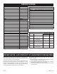
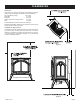
SPECIFICATIONS Model VFD10CC Input BTU/HR (KW/H) Maximum 10,000 FRBC Battery Operated Remote Control Input BTU/HR (KW/H) Minimum 10,000 FRBTC Battery Operated Remote Control w/Thermostat Height 24 1/8" (612.8 mm) FRBTP 7-Day Programmable Remote Width 21 1/2" (546.1 mm) FREC Electric Remote Control Depth 15 3/8" (390.5 mm) FWS Wall Switch Gas Inlet 3/8" (9.
PROVISIONS FOR ADEQUATE COMBUSTION & VENTILATION AIR This heater shall not be installed in a confined space or unusually tight construction unless provisions are provided for adequate combustion and ventilation air. A confined space is an area with volume less than 50 cubic feet per 1,000 Btuh of the combined input rates of all appliances drawing combustion air from that space. Small areas such as equipment rooms are confined spaces.
GAS SUPPLY Check all local codes for requirements, especially for the size and type of gas supply line required. Recommended Gas Pipe Diameter Pipe Length Schedule 40 Pipe Inside Diameter Tubing, Type L Outside Diameter Nat. L.P. Nat. L.P. 0-10 feet 0-3 meters 1/2” 12.7 mm 3/8” 9.5 mm 1/2” 12.7 mm 3/8” 9.5 mm 10-40 feet 4-12 meters 1/2” 12.7 mm 1/2” 12.7 mm 5/8” 15.9 mm 1/2” 12.7 mm 40-100 feet 13-30 meters 1/2” 12.7 mm 1/2” 12.7 mm 3/4” 19 mm 1/2” 12.
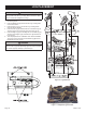
CLEARANCES Clearances When facing the front of the appliance the following minimum clearances to combustible construction must be maintained. Top of appliance (ceiling) 36 inches Rear Wall 2 inches Side Wall 6 inches Heater Corners (45° angle) to Wall 4 inches Floor 0 inches Provide adequate clearances around air openings. Adequate accessibility clearances for purposes of servicing and proper operation must be provided.
LOG PLACEMENT CAUTION Do not change the angle of the two Log Locating Tabs on the rear log shelf or the two Log Locating Tabs on the burner base. Doing so will cause misalignment of logs. 1. Place the Rear Log (A) onto the two Log Locating Tabs on the rear log shelf. 2. Place the Middle Log (B) behind the two Log Locating Tabs on the burner base. 3. Place the Front Log (C) onto the two Log Locating Extensions on the burner body. 4. Place the Left Log (D) onto the Left Pin on the Rear Log (A).
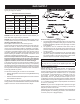
LOG IDENTIFICATION Log Set Identification Log Photo Part Number VFD10CC VFD20CC VFD30CC Index Letter Description 29553 29553 29546 A Rear Log 29554 29554 29547 B Middle Log 29555 29555 29548 C Front Log 29556 29556 29549 D Left Log 29558 29558 29551 E Right Log 29557 29557 29550 F Middle Top Log Note: Middle Top Log (F) is available as an optional log for the VFD10CC logsets. For more information, contact your Empire Dealer.
PLACEMENT OF GLOWING EMBERS (ROCK WOOL) Provided with the log set is a small bag of glowing embers (rock wool) to be placed between logs on the flat metal surface of the burner. Placement of the embers (rock wool) is very individual and light coverage of the areas indicated will provide your best effects. We recommend separation of the rock wool by hand and make your coverage as light and fluffy as possible. Place just enough embers (rock wool) on the burner to obtain the glow and a gold yellow flame.
OPERATING GUIDELINES Before operating this heater, please review the safety warnings pages at the beginning of this manual and those precautions and warnings listed below. 1. Know what type of ignition system this model has (standing pilot) and follow the applicable SAFETY and LIGHTING instructions. 2. Check to ensure there are no gas leaks. If you are unsure, turn gas off to the heater and call a service person or your gas utility.
MILLIVOLT LIGHTING INSTRUCTIONS FOR YOUR SAFETY READ BEFORE LIGHTING Warning: If you do not follow these instructions exactly, a fire or explosion may result causing property damage, personal injury or loss of life. A. This appliance has a pilot which must be lighted by hand. When lighting the pilot, follow these instructions exactly. B. BEFORE LIGHTING, smell all around the appliance area for gas. Be sure to smell next to the floor because some gas is heavier than air and will settle on the floor.
10,000 BTU MILLIVOLT LIGHTING INSTRUCTIONS FOR YOUR SAFETY READ BEFORE LIGHTING Warning: If you do not follow these instructions exactly, a fire or explosion may result causing property damage, personal injury or loss of life. A. This appliance has a pilot which must be lighted by hand. When lighting the pilot, follow these instructions exactly. B. BEFORE LIGHTING, smell all around the appliance area for gas.
PILOT FLAME CHARACTERISTICS Figures 10 and 12 show a correct pilot flame pattern. The correct flame will be blue and will extend beyond the thermocouple and thermopile. The flame will surround the thermocouple and thermopile just below the tip. A slight yellow flame may occur where the pilot flame and main burner flame meet. Figures 11 and 13 show an incorrect pilot flame pattern. The incorrect pilot flame is not touching the thermocouple or thermopile.
PILOT FLAME CHARACTERISTICS Cleaning and Pilot Maintenance Oxygen Depletion Sensor Pilot When the pilot has a large yellow tip flame, clean the Oxygen Depletion Sensor as follows: 1. 2. Clean the ODS pilot by loosening nut B from the pilot tubing. When this procedure is required, grasp nut A with an open end wrench. Blow air pressure through the holes indicated by the arrows. This will blow out foreign materials such as dust, lint and spider webs. Tighten nut B also by grasping nut A.
MILLIVOLT WIRING ON/OFF/REMOTE Switch This product is equipped with an ON/OFF/remote switch which is located on the wire channel. A wire harness is attached to the ON/OFF/REMOTE switch. The red, black and green (wires) female push-ons attach to the ON/OFF/REMOTE switch. At the opposite end of the wire harness, the black and green (wires) female pushons attach to the gas valve.
MILLIVOLT WIRING (continued) Wiring Diagram Figure 17 31208-1-1112 Page 19
MILLIVOLT TROUBLESHOOTING Symptoms - Possible causes and corrections important: Operating heater where impurities in air exist may create odors. Cleaning supplies, paint, paint remover, cigarette smoke, cements and glues, new carpet or textiles, etc., create fumes. These fumes may mix with combustion air and create odors. 1. When ignitor button is pressed, there is no spark at ODS/ pilot. a. Ignitor electrode positioned wrong - Replace ignitor. b. Ignitor electrode broken - Replace ignitor. c.
MILLIVOLT TROUBLESHOOTING (continued) 9. Slight smoke or odor during initial operation. a. Residues from manufacturing processes and logs curing Problem will stop after a few hours of operation. 10. Heater produces a whistling noise when main burner is lit. a. Turning control knob to HI position when main burner is cold - Turn control knob to LO position and let warm up for a minute. b. Air in gas line - Operate main burner until air is removed from line. Have gas line checked by local gas company. c.
IP OPERATING INSTRUCTIONS 5.25 VDC ELECTRONIC CONTROL VALVE 1. The electronic control valve system includes the ability to switch the pilot from a standing pilot mode to an intermittent pilot mode. • IPI Mode - In the Intermittent Pilot mode, when the unit is turned ON, it will cause spark to the pilot, light the pilot, then allow the burner to light. When the unit is turned to OFF, both the burner and pilot will be OFF.
IP WIRING If any of the original wire as supplied with this unit must be replaced, it must be replaced with equivalent gauge and temperature rated wire. This appliance is only for use with the type of gas indicated on the rating plate and may be installed in an aftermarket, permanently located, manufactured (mobile) home where not prohibited by local codes. This appliance is not convertible for use with other gases. CAUTION Do not operate the appliance with panel(s) removed, cracked or broken.
IP LIGHTING INSTRUCTIONS FOR YOUR SAFETY READ BEFORE LIGHTING Warning: If you do not follow these instructions exactly, a fire or explosion may result causing property damage, personal injury or loss of life. A. This appliance has a pilot which must be lighted by hand. When lighting the pilot, follow these instructions exactly. B. Before lighting smell all around the appliance area for gas. Be sure to smell next to the floor because some gas is heavier than air and will settle on the floor.
IP TROUBLESHOOTING Brief Description of the Components The gas valve is fitted with a manual HI/LO knob to allow for manual modulation of the gas outlet pressure to the appliance burner. The controls are designed to be used with either LPG or Natural Gas and can be converted by use of an OEM supplied conversion kit. The Digital Fireplace Control (DFC) is an automatic gas ignition system based on a single microcontroller core.
IP TROUBLESHOOTING Page 26 31208-1-1112
IP TROUBLESHOOTING 31208-1-1112 Page 27
MAIN BURNER FLAME CHARACTERISTICS Figure 19 shows a correct main burner flame pattern. Figure 20 shows an incorrect main burner flame pattern. If main burner flame pattern is incorrect, as shown in Figure 22: • See Troubleshooting, pages 20 and 21 for millivolt models and pages 25 - 27 for IP models. Cleaning and Maintenance / Main Burner WARNING Turn off heater and let cool before cleaning. After use, cleaning of the main burner may be required for the proper flame.
MAINTENANCE IMPORTANT: Turn off gas before servicing appliance. It is recommended that a qualified service technician perform these check-ups at the beginning of each heating season. • Clean Burner and Control Compartment Keep the control compartment, logs and burner area surrounding the logs clean by vacuuming or brushing at least twice a year. Cleaning Procedure 1. Turn off pilot light at gas valve. 2. Remove screen front. (two 10 x 1/2" screws) 3.
PARTS LIST - VFD10CC(30,70) PLEASE NOTE: When ordering parts, it is very important that part number and description of part coincide. INDEX NO. PART NO. DESCRIPTION INDEX NO. PART NO.
PARTS VIEW - VFD10CC(30,70) 2 3 4 5 6 7 8 1 9 12 11 25 11 10 12 13 17 14 16 14 21 15 21 18 18 19 20 19 20 22 23 31208-1-1112 17 16 24 Page 31
PARTS LIST - VFD20CC(30,70) PLEASE NOTE: When ordering parts, it is very important that part number and description of part coincide. INDEX NO. PART NO. DESCRIPTION INDEX NO. PART NO.
PARTS VIEW - VFD20CC(30,70) 1 2 3 4 5 6 7 8 9 11 11 10 12 12 13 17 14 16 21 14 16 15 17 21 18 18 19 20 20 19 22 23 31208-1-1112 24 Page 33
PARTS LIST - VFD30CC(30,70) PLEASE NOTE: When ordering parts, it is very important that part number and description of part coincide. INDEX NO. PART NO. DESCRIPTION INDEX NO. VFD30CC30(B,F,M,S,W)(N,P) PART NO.
PARTS VIEW - VFD30CC(30,70) 1 2 3 4 5 6 7 8 9 11 11 10 12 12 13 17 14 16 21 14 16 15 17 21 18 18 19 20 20 19 22 23 31208-1-1112 24 Page 35
CASTING PARTS LIST - VFD(10,20,30)CC(30,70) PLEASE NOTE: When ordering parts, it is very important that part number and description of part coincide. INDEX NO. PART NO. DESCRIPTION INDEX NO. PART NO.
CASTING PARTS VIEW - VFD(10,20,30)CC(30,70) 1 2 3 4 11 6 11 5 10 7 11 10 11 12 8 13 9 12 13 31208-1-1112 Page 37
MASTER PARTS DISTRIBUTOR LIST To Order Parts Under Warranty, please contact your local Empire dealer. See the dealer locator at www.empirecomfort. com. To provide warranty service, your dealer will need your name and address, purchase date and serial number, and the nature of the problem with the unit. To Order Parts After the Warranty Period, please contact your dealer or one of the Master Parts Distributors listed below. This list changes from time to time.
ACCESSORY SIDE SHELVES INSTALLATION INSTRUCTIONS Installing Accessory Side Shelves: 1. Remove cast iron or stone inlay inserts from casting top and carefully set them aside. 2. Remove cast iron top from stove and place upside down on a flat, soft smooth surface to avoid damage. 3. Remove four ¼-20 hex head bolts from the outer edges of cast iron top. 4. Place left and right side shelves in place shown in Figure 22. 5.
CIB4-1 OPTIONAL BLOWER INSTALLATION INSTRUCTIONS CAUTION Sharp edges, use protective gloves when installing. Installation 1. Loosen, but do not remove, four hex-head screws located on the exterior, bottom of the appliance. 2. Position the blower assembly at the rear of the appliance. The blower assembly has four keyholes for attachment to the exterior, bottom of the appliance. 3. Place the large diameter holes in the keyholes over and behind the four hex-head screws that were loosened in Step 1.
CIB4-1 OPTIONAL BLOWER INSTALLATION INSTRUCTIONS Cleaning The blower wheel will collect lint and could require cleaning once a year. If the air output decreases or the noise level increases, it indicates a dirty wheel. Blower Motor The blower motor does not have oiling holes. Do not attempt to oil blower motor.
CIB3-1 OPTIONAL BLOWER INSTALLATION INSTRUCTIONS 6. CAUTION Sharp edges, use protective gloves when installing. Installation 1. Loosen, but do not remove, four hex-head screws located on the exterior, bottom of the appliance. 2. Position the blower assembly at the rear of the appliance. The blower assembly has four keyholes for attachment to the exterior, bottom of the appliance. 3. Place the large diameter holes in the keyholes over and behind the four hex-head screws that were loosened in Step 1.
CIB3-1 OPTIONAL BLOWER INSTALLATION INSTRUCTIONS Fan Control The fan control is a non-adjustable automatic type The fan control will require between 5 and 10 minutes of main burner operation before the fan control "closes" and activates the blower. The blower will continue to run between 5 and 10 minutes after the main burner shuts off, before the fan control "opens" and deactivates the blower. Cleaning The blower wheel will collect lint and could require cleaning once a year.
WARRANTY Empire Comfort Systems Inc. warranties this hearth product to be free from defects at the time of purchase and for the periods specified below. Hearth products must be installed by a qualified technician and must be maintained and operated safely, in accordance with the instructions in the owner’s manual. This warranty applies to the original purchaser only and is not transferable. All warranty repairs must be accomplished by a qualified gas appliance technician.
APPLIANCE SERVICE HISTORY Date Dealer Name 31208-1-1112 Service Technician Name Service Performed/Notes Page 45
EMPIRE Web Site: www.empirecomfort.
EMPIRE Empire Comfort Systems 918 Freeburg Avenue Belleville, Illinois 62220-2623 Web Site: www.empirecomfort.com Comfort Systems The Heritage Cast Iron Stoves Models: VFD(10,20)CC(30,70)(B,F,M)N,P)-1 and VFD30CC(30,70)B,F,M,S,W)(N,P)-1 Clearances In selecting a location for installation, it is necessary to provide adequate accessibility clearances for servicing and proper operation.
EMPIRE Comfort Systems Empire Comfort Systems Inc. 918 Freeburg Ave. Belleville, IL 62220 If you have a general question about our products, please e-mail us at info@empirecomfort.com. If you have a service or repair question, please contact your dealer. www.empirecomfort.