
Data Sheet


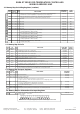

2.MODBUS ERROR MESSAGES
Modbus protocol has two types error, communication error and operating error. Reason of the communication error is
data corruption in transmission. Parity and CRC control should be done to prevent communication error. Receiver side
checks parity and CRC of the data. If they are wrong, the message will be ignored. If format of the data is true but
function doesn’t perform for any reason, operating error occurs. Slave realizes error and sends error message. Most
significant bit of function is changed '1' to indicate error in error message by slave. Error code is sent in data section.
Master realizes error type via this message.
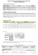
Error Code
Meaning
Name
ILLEGAL FUNCTION
ILLEGAL DATA ADDRESS
ILLEGAL DATA VALUE
01
02
03
The function code received in the query is not an allowable action for the slave. If a
Poll Program Complete command was issued, this code indicates that no program
function preceded it.
The data address received in the query is not an allowable address for the slave.
A value contained in the query data field is not an allowable value for the slave.
Device Address
Function Code
Beginning address
of coils.
Number of coils (N)
CRC DATA
MSB
LSB
MSB
LSB
LSB
MSB
Structure of command message (Byte Format)
(0A)h
(01)h
(04)h
(A1)h
(00)h
(01)h
(AC)h
(63)h
Device Address
Function Code
CRC DATA
LSB
MSB
Structure of response message (Byte Format)
(0A)h
(81)h
(02)h
(B0)h
(53)h
Error Code
Message example;
As you see in command message, coil information of (4A1)h = 1185 is required but there isn’t any coil with 1185 address.
Therefore error code with number (02) ( ) sends.Illegal Data Address
ModBus Error Codes
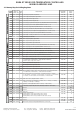
1.5 Memory Map for Discrete input
Discrete nputI
Addresses
Read Only
Read Only
Read Only
Read Only
C/A2 Control output status (0 = OFF ,1 = ON)
A1 (0 = OFF , 1 = ON )Output status
SSR (0 = OFF ,1 = ON)Output status
Digital input status (0 = OFF ,1 = ON)
Parametre
Numarasi
Data
Type
D0
D1
D2
D3
Bit
Bit
Bit
Bit
(0000)h
(0001)h
(0002)h
(000 )h3
Data Content
Read / Write
Permission
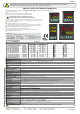
ENDA ET SERIES PID TEMPERATURE CONTROLLER
MODBUS ADDRESS MAP
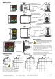
* MODBUS CONNECTION DIAGRAM
120 Ohm
Master
Slave - 1
Up to 127 slave devices
can be controlled.
Slave - 2
Slave - 127
-
A
B
-
A
B
-
A
B
-
A
B
Termination should be accomplished by
attaching 120 Ohm resistors to the start
and at the end of the communication line.
* Applies to devices with Modbus function.
E-mail : info@suran-elektronik.de
Internet : www.suran-elektronik.de
Tel.: +49 (0)7451 / 625 617
Fax: +49 (0)7451 / 625 0650
SURAN Industrieelektronik
/ D-72160 Horb a.NDettinger Str. 9
ETx420-E-Modbus-10052019
3. / 3