
Product Manual

SlickBracket 66
MOUNTING
INSTRUCTIONS
1. Use M6 or 1/4" counter-sunk head screws with a
length of 30mm (SlickBracket) plus washer and
nut, plus the thickness of the mounting and the
backing plate or strip. (1-1/4" plus mounting and
backing plate). MAKE SURE THE BASE PLATE
IS SHIMMED LEVEL AND DOES NOT SHIFT
OR DISTORT WHEN THE BOLTS ARE
TIGHTENED DOWN,
2. Use the SlickBracket top or base plate as a
pattern for the holes in the mounting location and
drill 6 holes.
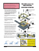
3. Assembly the SlickBracket together as shown.
Before putting on the top plate fit the two lock
bars over the posts of the base.
Make sure both lock bar notches
face inward and at the lock pin end
of the base.
4. Install the lock pins as shown in the
slots in the base. One pin fits upside
down under the top pin.
5. Add the top plate and install the 6 screws to hold
the assembly together. Install the assembly into
the holes in the mounting location. On a vertical
mounting surface, make sure the lock bars are
pointing down in the lock position so any
vibration will not open the SlickBracket. Fit the
backing plate or strip, washers and nuts to the
screws underneath the mounting surface.
6. Tighten down the assembly until the lock bars
slide back and forth with a good push. This
prevents rattling under boat/vehicle movement.
The SlickBracket plastic posts on the baseplate
are designed to compress to make this
adjustment. If there is not enough adjustment,
put spacer washers (supplied) under the top
plate to increase the thickness.
TO LOCK
Use thumb and finger
lift up and squeeze
TO UNLOCK
Use thumb and finger
lift up and squeeze
HOW THE LOCK PINS WORK
Insert Padlock
Pin
MAXIMUM SAFE LOADING depends on the
type of insert used. Generally use 50% steel
loading if aluminum inserts are used.
IMPORTANT
The mounting of a SlickBracket is only as strong and
secure as the bolts and the mounting structure. Always use
high quality stainless or steel bolts and lock nuts.
Always put a backing plate under the mounting surface to
spread the load over a larger area than bolt washers.
Wood screws or lag bolts are not recommended for heavy
loads. Keep these loads under 150 lbs (70kg)
M6 or 1/4” csk hd screws
Length to suit mounting
not supplied
Top Plate
Use as a guide to
drill mounting holes
Lock bars with notch
inward
Baseplate
Lock Pins
Padlock pin
Backing plate not
supplied
Washers and nuts
not suppled
Brackets at right angles
to lock bars
1100 lbs (500 kg)
1100 lbs (500 kg)
1600lbs (725 kg)
Optional
top bar
spacer
washers
top plate
base
plate
lock
bar
Post Spacers
The lock bars should be able
move with some resistance
when the mounting screws
are tightened down. Spacer
washers (0.5 and 1mm) are
provided for mounting on an
uneven surface or differences
in bolt tightening. Adjust all 6
posts to suit.