
Operating Guide

For use with EN31260 / EN32430 Series Chargers operating in parallel:
• To install the optional Remote Display in a specic location, two 6 pin standard RJ12 cables (maximum
length 7.5m) are required. (NOTE: Only one RJ12 Cable Is Supplied with Remote).
• Install the two standard RJ12 cables in parallel in your desired location.
• For the rst RJ12 cable, connect one end to the Digital Display port of Charger_1 and the other end to
Remote Display Panel COM_1 Port.
• For the second RJ12 cable, connect one end to the Digital Display port of Charger_2 and the other end to
Remote Display Panel COM_2 Port.
• The Remote Display is now ready for use.
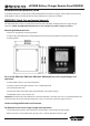
Note 1: With AC Input available, both Digital Displays will show ‘CON’ indicating the two chargers are
connected in parallel. The ‘INFO’, ‘NEXT’ and ‘SET’ push buttons on both chargers are disabled. With AC
Input not available, press and hold the ‘INFO’ button on Charger_1 will show battery voltage of Bank 1, 2, 3
and then follow with charger rmware revision.
Note2: The combined chargers setting are based on the original setting on Charger 1. To readjust the
combined charger setting, it has to be done through the Remote Display. Before connecting the batteries
to the chargers, Battery Bank 1 of Charger_1 has to connect to Battery Bank 1 of Charger_2. Battery Bank 2
ofCharger_1 has to connect to Battery Bank 2 of Charger_2and Battery Bank 3 of Charger_1 has to connect
to Battery Bank 3 of Charger 2. The Common Ground of both chargers has to be connected together.
Damage to both chargers may occur with wrong connection if the above connections are not follows.
Tips: During installation or unit setting, it is recommended to pre-set the desire charger setting on Charger_1
rst before connect the 2nd RJ12 cable to Charger_2, as once Charger_2 is connected, all the three push
button on the charger is disable and the display will only show ‘Con’ and the setting can only be adjusted
by using the Remote Panel.
Important: The charger that is connected to ‘Com 1’ of the Remote Panel is the master control.
• Connect one end of the second RJ12 cable to ‘Com 2’ of Remote Panel.
• Connect the other end of RJ12 cable to the ‘Remote’ Port of the second charger (Charger_2).
Important: The two Chargers that are connected in parallel must be the same model and rating even if some
of the banks may not be in use.
• Connect Battery Bank 1, 2, 3 of Charger_1 to Battery Bank 1, 2, 3 of Charger_2 respectively.
Important: Incorrect connection of dierent banks between the two chargers may damage the units.
• Connect the Common Ground of both chargers together.
Important: If Battery Temperature Sensor is in use, two battery temperature sensors are required. Connect the
rst battery sensor connected to Charger_1 to the positive terminal of Bank 1 and the second battery sensor
connected to Charger_2 to the negative terminal of Bank 1.
Page 2 (Version 3) - Aug 2015