Owner’s Manual Enerdrive ePOWER DC2DC+ Battery Charger Owner’s Manual (Rev. 1.
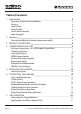
Table of Contents 1. Introduction 4 Please Keep This Manual For Future Reference 4 Disclaimer 4 Important Note 4 Product Numbers 4 Service Contact Information 4 Notice of Copyright 5 2. Warnings 6 Please read and follow the instructions and precautions carefully. 6 3. PRODUCT DESCRIPTION 8 4.
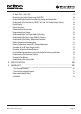
DC Input (CH2 – Solar / PV): 23 Maximising your Solar Harvest using the DC2DC+ 24 Understanding the Display & Function Keys during normal operation 25 Understanding The Function Key ‘MENU’, ‘SET’ And ‘SEL’ During Charger Setting 26 Digital Display: 26 Button Functions: 27 Automatic Override Functions: 28 Programming Your Charger 28 Understanding the Two-Stage (Mode 2) Charging 28 Understanding The Three-Stage (Mode 3) Charging 28 Understanding The Battery Temperature Functions 28 Battery Tempera
1. INTRODUCTION Thank you for purchasing the Enerdrive ePOWER DC2DC+ Battery Charger. With our state of the art, easy to use design, this product will offer you reliable service for providing a multistage, multi-input battery charger to charge the different types of batteries you have installed in either your home, boat, caravan, 4WD or commercial vehicle. This manual will explain how to use this unit safely and effectively.
Notice of Copyright Enerdrive ePOWER DC2DC+ Battery Charger owner’s manual © 2017 Enerdrive. All rights reserved. No part of this document may be reproduced in any form or disclosed to third parties without the express written permission of Enerdrive Pty Ltd, P.O. Box 9159, Wynnum Plaza, Queensland, Australia 4178.
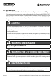
2. WARNINGS Please read and follow the instructions and precautions carefully. This section contains important safety information for the Enerdrive ePOWER DC2DC+ Battery Charger. Each time, before using the Enerdrive ePOWER DC2DC+ Battery Charger. READ ALL instructions and cautionary markings on or provided with the DC2DC+ Battery Charger, and all appropriate sections of this guide. CAUTION This unit is intended for indoor use ONLY.
WARNING Explosion Hazard! DO NOT use the Enerdrive ePOWER DC2DC+ Battery Charger in the vicinity of flammable fumes or gases (such as gas bottles). AVOID covering the ventilation openings. Always operate unit in an open and well ventilated area. Prolonged contact to high heat or freezing temperatures will decrease the working life of the unit.
3. PRODUCT DESCRIPTION The Enerdrive ePOWER DC2DC+ Battery Charger is a multistage, multi-input battery charger to charge different types of batteries commonly installed in either boat’s, caravan’s, 4WD’s or commercial vehicle’s. Enerdrive’s ePOWER DC2DC+ Battery Charger package includes the following items; 1 x ePOWER DC2DC+ Battery Charger 1 x Battery Temperature Sensor 7.5 Meter Cable) Owner’s Manual 1 x Owner’s manual Enerdrive ePOWER DC2DC+ Battery Charger Owner’s Manual (Rev. 1.
4. UNDERSTANDING THE UNIT The Enerdrive ePOWER DC2DC+ Battery Charger is a fully automatic multistage, multi input battery charger with the ability to charge from either an alternator linked to a battery; or via solar power with the in built Maximum Power Point Tracking (MPPT) Solar Controller. With two inputs available, the house battery will be charged from either the engine while underway, or via the solar panels when stationary.
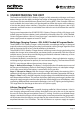
additional loads connected to the battery while the DC2DC+ is powered from either the vehicle or solar inputs. A Bulk re-start will occur when battery voltage drops below 13.3V DC. Smart Charging Feature The ePOWER DC2DC+ Battery Charger will regulate its output based on the loads connected to your battery banks.
Lithium Battery charging algorithm Battery Current Bulk Power Supply Mode Maint. Power Supply Mode Battery Voltage Return to Bulk 14.4V 14.2V 14.0V 13.8V 13.6V 13.4V 13.3VDC triggers Bulk Restart 13.2V 13.0V Time out 8 hrs max 12.8V Time out 7 days Diagram does not illustrate our current set points. Note: Actual voltages depend on chosen algorithm. Battery Charger Voltage Battery Type Absorption Float (See Note 3) Equalisation GEL 14.4 V 13.7 V N.A. AGM 14.6 V 13.6 V N.A.
NOTE: The equalisation function although included in the ePOWER DC2DC+ will rarely be used. To activate, the battery bank must be in float, and manually activated. A typical drive will not be long enough for the DC2DC function to complete the process. The MPPT Solar function may provide enough time for Equalisation, but the best recommendation will be an AC powered battery charger. Battery Bank Size Recommendation The battery charging current rating is based on the battery size.
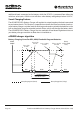
5. INSTALLING THE CHARGER WARNING Enerdrive recommends that all wiring be done by a skilled technician to ensure adherence to the best practice standards for on-board DC electrical installations. Failure to follow these instructions can damage the unit and could also result in personal injury or loss of life.
Mounting The Charger • Choose an appropriate mounting location. • For installing in an indoor location, the unit should be mounted vertically (with the battery terminals facing downwards). This provides the best thermal performance and drip protection. The unit should NOT be mounted upside down. • For installing in a boat or marine environment, the unit should only be mounted vertically (Battery Terminals facing downwards only) to provide adequate drip protection.
6. CONNECTING THE CHARGER Chassis Grounding Connection BEST PRACTICE This Charger SHOULD BE CORRECTLY GROUNDED. The unit chassis has a stud point on it for grounding. Connect the unit’s chassis ground to the common ground point through the ground stud located near one of the unit mounting slots. (Battery DC negative is the best ground reference point in your installation) . DC Output Wiring WARNING: Correct DC Wiring Is Required The DC wiring used must be of appropriate size.
DC2DC+ Battery Charger Connections Battery Temperature Sensor Port Unit Ground IGNITION SENSE TERMINAL Page 16 BATTERY INPUT BATTERY INPUT SOLAR INPUT SOLAR INPUT BATTERY OUTPUT BATTERY OUTPUT CH3 CH2 CH1 Start Battery Solar Array House Battery Enerdrive ePOWER DC2DC+ Battery Charger Owners Manual (Rev. 1.
Recommended Cable Length, Size and Fuse Protection.
Recommended Fuse Protection From Alternator Battery From Solar Panels Primary Battery Connection 70amp Fuse or Circuit Breaker no greater than 20cm from source battery. PLEASE NOTE: Automatic re-settable circuit breakers are NOT recommended. Fusing recommended no greater than 20cm from input to DC2DC+ Charger. Typically 15amps per solar panel (consult your panel specifications for further details). 60amp Fuse or Circuit Breaker.
Battery Wiring (Towing Applications): For Towed Applications i.e. Caravans, Camper Trailers Please NOTE The negative cable from the start battery must be carried to the DC2DC input terminal for correct operation in a towed application.
Battery Wiring (Vehicle & Marine Applications): For In Vehicle & Marine Installation. i.e. Motorhomes, 4WD’s & Trucks. Please NOTE Vehicles with a Smart alternator, the Negative cable must be connected to the vehicle side of the Battery Sense Module. (Optional Ignition - On) VSO (Voltage Sense Override) Fuse Size 1A Temp Sensor Cable (Included) Fuse / Breaker 12V - 70A 24V - 40A Smart alternator battery sense module.
7. UNIT OPERATION Understanding The Charging Mechanism Note 1: The Charger is powered by the battery connected to DC Output (CH1) and also supplied by CH2 or CH3 if available. The display will turn off to save power when Input Channel CH2 and CH3 are out of operating range.
current. This function is used to compensate for the use of long or thin wire between the Input Battery System and the unit input terminals. If the input voltage continues to drop below the <10.5V for a 12V system (<21V for a 24V system), the charging process will terminate and the unit will switch back to charge from CH2 (solar if installed) if installed. It will only switch back to CH3 if the CH3 voltage is >13.2V on a 12V system (>26.4V on a 24V system.
DC Input (CH2 – Solar / PV): PV Input Voltage Range 14.5 - 45V PV Input Under Voltage Shutdown < 14.5V PV Input Under Voltage Recovery 15.0V PV Input Over Voltage Shutdown > 45V PV Input Over Voltage Recovery = < 44V PV Charging Mechanism Maximum Input MPPT type ( approx. 97% efficiency) 500W *See Note below and “Maximising your Solar Harvest using the DC2DC+“ *Note: The recommended maximum solar wattage input for the DC2DC+ Charger is 500w. You can however “overdrive” the MPPT controller.
Maximising your Solar Harvest using the DC2DC+ The Solar Input on the DC2DC+ unit has a maximum rated INPUT current of 30amps. This means it is optimised for using higher voltage ‘grid’ type modules for best output performance The maximum achievable output using standard 20Voc solar modules will be approximately 35amps @ 14.4Vdc output.
Understanding the Display & Function Keys during normal operation Display Digital Display LCD with back lighting Digital Display Info : CH1 CH2 & CH3 Fault/Warning Charging Status, Voltage, Current Voltage Error code E01-08, Warning A01-02 ‘CH3’ Icon Flashing CH3 > 12.0V on a 12V Input system CH3 > 24.0V on a 24V Input system and not charging from (alternator) ‘CH3’ Icon Solid Charging from CH3 input (Start Battery / Alternator) ‘CH2’ Icon Flashing CH2 > 14.
Understanding The Function Key ‘MENU’, ‘SET’ And ‘SEL’ During Charger Setting CH1 - display is showing the charging battery info (charging status, voltage and current). CH2 or CH3 - When displayed symbol is solid this means the power is coming from the related channel and the other channel will be flashing if it is connected but not charging.
Button Functions: • During normal charging operation, press once to change the display to show • CH1, CH2 and CH3 voltage. • During normal charging operation, press and hold for more than 3 seconds to enter Charger Function Setting Menu • When CH2 or CH3 is not available (voltage detect is below the sense voltage), display will turn OFF. Press once will temporary trigger on the display and it will automatically cycle through all three channels voltage, the software revision and then turn off.
Automatic Override Functions: When positive power is applied to the “Ignition Sense” terminal (do not connect to ground), it will force the charger to connect to CH3 as long as CH3 is within the voltage range >12.3V or 24.6V on a 24v input. Programming Your Charger Press and hold the key for longer than 3 seconds to enter charger setting mode and show function setting. Once new setting is done, press ‘MENU’ again for longer than 3 seconds to exit the charger setting mode.
temperature and overrides the manual temperature settings and makes small adjustments to the charging voltage. If using lithium batteries, leave temp set to “NOR” (Normal) and leave temp sensor disconnected. Battery Temperature Compensation: There are three manual battery temperature settings on the unit (‘Lo’, ‘nor’ and ‘hi’). See the table below for voltage adjustments for temperature compensation.
Procedure To Equalise Flooded Batteries DANGER Explosion Hazard And Risk Of Battery Damage. The battery generates explosive gases during equalisation. Follow all the battery safety precautions listed in the manual. When using the equalisation mode, the user has to be sure the battery connected to the battery charger is a flooded battery type. Equalizing a non-flooded battery may overcharge the battery and may cause the battery to explode. CAUTION Risk of battery and equipment damage.
Understanding The Protection Features De-rating Charging Current: When the charger senses the environmental temperature is above 50°C, the maximum charger current will de-rate to 1/2 of the set value (A01 warning code will display). The charger will recover automatically back to maximum charging current when the environmental temperature drops to below 45°C. Over Temperature Shutdown: When the charger senses the environmental temperature is above 60°C, the charger will shutdown.
Page 32 E01 CH3 High Input Voltage Shutdown This means the unit has detected the input from the Start/Alternator has gone above 16.0V on a 12V input or 32.0V on a 24V input. This error will clear once the input has dropped below 15.5V on a 12V input or 31.0V on a 24V input. E02 CH3 Low Input Voltage Shutdown This means the unit has detected that the input from the Start/Alternator has gone below 10.5V on a 12V input or 21.0V on a 24V input. This error will clear once the input has risen above 13.
E08 CH1 Output Short Circuit This means there is a Short Circuit on the DC output to your Main/House battery. If this is displayed, check the following: • The output wires are not shorted together. • The output wires are wired correctly and not reverse polarity. A01 Over Temperature Warning When the charger’s internal temperature is > 60°C, the unit will shut down to protect itself.
8. SPECIFICATIONS Output Rating Output Voltage 12V Nominal (8.0V min) Output Current 40A ~ 50A Output Power 775W Charger DC Output (CH1): Selectable Battery Type Gel, AGM, Flooded, Lithium, Program Charger Voltage Range 13.8V – 15.5V Float Voltage Range 13.0V – 13.8V Charger Current (User Selectable) 5/10/15/20/25/30/35/40/45/50A (default 40A) Equalize Voltage (Flooded Battery) 15.
9. WARRANTY 2 Year Limited Warranty Our goods come with guarantees that cannot be excluded under the Australian Consumer Law. You are entitled to a replacement or refund for a major failure and for compensation for any other reasonably foreseeable loss or damage. You are also entitled to have the goods repaired or replaced if the goods fail to be of acceptable quality and the failure does not amount to a major failure.
If such a unit is returned more than 30 days but less than two years from the purchase date, Enerdrive will repair the unit or, at its option, replace it, free of charge. If the unit is repaired, new or reconditioned replacement parts may be used, at manufacturer’s option. A unit may be replaced with a new or reconditioned unit of the same or comparable design. The repaired or replaced unit will then be warranted under these terms for the remainder of the warranty period.
www.enerdrive.com.
to change battery type Press SET to keep the current setting and toggle to the next menu Display shows Bulk Current as to enter high currently set. current menu Press SEL Press SET to keep the current setting and toggle to the next menu Display shows GEL & Bulk Voltage as currently set.
CH1 ABSORPTION TO FLOAT CURRENT CH1 CHARGE MODE CH1 TEMP.
to change battery type Press SEL Display shows the Float voltage for Program. to enter Voltage Menu Press SEL (13.0V to 13.8V in 0.1V steps) Press SEL to change voltage Press SET to keep the current setting and toggle to the next menu to return to change voltage Press SEL Press SET to keep the current setting and toggle to the next menu to return to voltage (13.9V to 14.6V in 0.
CH1 LITHIUM CHARGING CURRENT Press SET to keep the current setting and toggle to the next menu CH1 Absorption to Float Current “L” Setting This setting is used to determine when the battery is full. Once the current flow reaches this number or below, the charger deems the battery to be full and will shift the charger to the float state. If running constants loads i.e.
Press SEL to enter Voltage Menu Press SET to keep the current setting and toggle to the next menu Display shows the Float voltage for Program. Press SEL Press SET to keep the current setting and toggle to the next menu Display shows Program & Bulk to enter Voltage as currently set. Voltage Menu Press SEL Press SET to keep the current setting and toggle to the next menu to change battery type Continues from Appendix A2 CH1 Battery Type Menu VERSION: REV. 1.
CH1 PROGRAM BULK CURRENT CH1 PROGRAM ABSORPTION TO FLOAT CURRENT CH1 CHARGE MODE Press SET to keep the current setting and toggle to the next menu to change mode Press SET to keep the current setting and toggle to the next menu to return to change mode Press SEL CH1 Absorption to Float Current “L” Setting This setting is used to determine when the battery is full.
Fill in the details below for your reference and convenience. Serial Number: Date of Purchase: Purchased From: Page 44 Enerdrive ePOWER DC2DC+ Battery Charger Owners Manual (Rev. 1.
Notes: www.enerdrive.com.
Notes: Page 46 Enerdrive ePOWER DC2DC+ Battery Charger Owners Manual (Rev. 1.
Notes: www.enerdrive.com.
ENERDRIVE PTY LTD P.O. Box 9159, Wynnum Plaza, Queensland, Australia 4178 Ph: 1300 851 535 / Fax: 07 3390 6911 Email: support@enerdrive.com.au Web: www.enerdrive.com.