
Manual

2
WARNING: Only use hydraulic cylinders in a coupled
system. Never use a cylinder with unconnected couplers.
If the cylinder becomes extremely overloaded,
components can fail catastrophically causing severe personal
injury.
WARNING: BE SURE SETUP IS STABLE BEFORE
LIFTING LOAD. Cylinders should be placed on a flat
surface that can support the load. Where applicable, use a
cylinder base for added stability. Do not weld or otherwise
modify the cylinder to attach a base or other support.
Avoid situations where loads are not directly centered on
the cylinder plunger. Off-center loads produce
considerable strain on cylinders and plungers. In addition,
the load may slip or fall, causing potentially dangerous results.
Distribute the load evenly across the entire saddle
surface. Always use a saddle to protect the plunger.
IMPORTANT: Hydraulic equipment must only be serviced
by a qualified hydraulic technician. For repair service,
contact the Authorized ENERPAC Service Center in your
area. To protect your warranty, use only ENERPAC oil.
WARNING: Immediately replace worn or damaged parts
with genuine ENERPAC parts. Standard grade parts will
break causing personal injury and property damage.
ENERPAC parts are designed to fit properly and withstand high
loads.
3.0 GENERAL INFORMATION
The Enerpac valve design incorporates the following features into
a single unit:
• 10,000 psi [700 bar] operating pressure
• Load holding
• The Enerpac valves are specifically designed for use with
Enerpac pumps
• User adjustable relief valve
• Gauge ports
3.1 Capacity
Capacity is 900 cu. in/min (14.8 l/min) [3.9 gpm].
CAUTION: If using pipe sealants on male pipe threads,
use sparingly and never over ends of fittings where it can
be torn loose and get into system.
4.0 INSTALLATION
1. Install valve onto Enerpac pump using gasket and fasteners
included. Take needed steps to ensure pump's pressure tube
o-ring and backup are not damaged.
CAUTION: If you are not trained and familiar with installing
a valve have an Authorized Enerpac Service Center
perform this step.
2. Install pressure gauge, if required, into proper port. Pressure
can be monitored at the “GP” ports, the “GB” port or the “GA”
port or any combination of these, depending on system
requirements.
CAUTION: If using pipe sealants on male pipe threads, use
sparingly and never over ends of fittings where it can be
torn loose and get into the hydraulic system.
5.0 OPERATION
1. Connect and secure hoses and cylinders noting that the
proper ports are connected.
2. Quick disconnects must be fully engaged and locking collars
drawn up fully to ensure free flow of oil between valve and
attached component.
3. Place valve handle in proper position before starting pump.
Tandem centered valves should be in “neutral” position.
Closed centered valves should be in a position which will
ensure a safe start up when the pump is started.
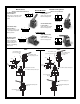
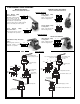
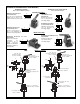
VM33, VM33L, VM43,
VM43L (See Fig. 1)
1. Advance
2. Retract
3. Neutral
4. Valves equipped with a positive locking feature will not permit
movement of the load when the handle is moved between
positions (VC3L, VC15L, VM3L, VM33L, VC4L, VC20L,
VM4L, VM43L). Valves not equipped with this feature will
lower or drop the load during handle movement. The amount
of loss or load movement will depend on the speed of handle
movement between detent positions.
5. VM33, VM43 valves are equipped with an integral system
check valve. To "hold" load, keep valve handle in position and
simply turn pump off. Rotate handle to lower load.
NOTE: Enerpac valves are either tandem or closed center.
Tandem centered valves allow oil to flow from the pump to
tank when in the NEUTRAL position. Closed centered
valves block the flow of oil from the pump when in the
NEUTRAL position. Selecting the type of valve that best
meets your needs is important for satisfactory operation.
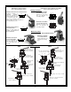
5.1 Relief Valve Adjustment (Models VM33/33L/43/43L)
Z-Class pumps are equipped with one user adjustable relief
valve (see Figure 2.) It can be adjusted as follows:
1. Install a gauge on the pump. If a unit is equipped with optional
pressure transducer, verify “SET PRES” valve is higher than
desired relief valve setting or Auto Mode is off.
2. Start the pump to allow the oil to warm.
3. Loosen the set screw locking nut.
4. Shift the valve and build pressure in the system. Using an
Allen wrench, turn the set screw counter-clockwise to
decrease pressure and clockwise to increase pressure.
NOTE: To get an accurate setting, decrease the pressure to
a point below the final setting and then slowly increase the
pressure until it reaches the final setting.
5. Tighten the locking nut when the desired pressure is set.
6. Shift the valve to the neutral position, allowing the system
pressure to return to 0 psi.
7. Recheck the final pressure setting by shifting the valve and
pressurizing the system.
®
3 - In Use
1
3
2
A
B
Figure 1