
Owner`s manual

COMBUSTION AIR SUPPLY
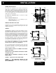
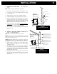
For a mobile home installation the stove must be connected to an
outside source of combustion air. A 3” inside diameter metallic pipe,
either flexible or rigid, may be attached to the inlet at the stove’s rear
(refer to figures 4, 5 & 6). A rodent guard (minimum ¼” wire mesh)
must be used at the terminus (refer to figure 5). All connections must
be secured and airtight by either using the appropriately sized hose
clamp and/or UL-181-AP foil tape.
For mobile home installations only: No combustion air supply
may exceed 10 feet.
Sources of Outside Combustion Air
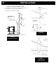
• A hole in floor near stove rear terminating only in a
ventilated crawl space.
• A hole in the wall behind the stove.
WHEN OUTSIDE AIR IS NOT USED
If outside air is not used, it is important that combustion air be easily
available to the air inlet. A closeable outside air register can be used
in tightly insulated homes.
VENTING
The BIO-45 MF is certified for use with a vent certified to UL-103 or
ULC S629M and a chimney type vent certified to UL-641 or ULC-S-
609-M89 and ULC/ORD C441-M90, with 3” or 4” inner diameter. In
Canada, we recommend that you use a listed pellet vent that meets
the ULC S-609-M89 and ULC/ORD C441-M90 Standards. For the
United States, we recommend that you use a listed pellet vent that
meets the UL-641, 7
th
edition Standard. This unit can be vented in
an existing chimney with the addition of a liner if the chimney is
more than 4” in diameter. Class “A” chimney is not required. Refer
to the instructions provided by the vent or chimney manufacturer,
especially when passing through a wall, ceiling, or roof.
Your venting system should have at least one foot of vertical
rise for each foot of horizontal run. The total vertical rise
should never be less than 3 feet (see Appendix A).
This is a pressurized exhaust system. All vent connector joints must
be sealed and fastened in accordance with the pellet pipe
manufacturer's instructions to ensure consistent performance and
avoid smoke and ash spillage.
DO NOT CONNECT THIS UNIT TO A CHIMNEY FLUE SERVING
ANOTHER APPLIANCE.
DO NOT INSTALL A FLUE DAMPER IN THE EXHAUST VENTING
SYSTEM OF THIS UNIT.
INSTALL VENT AT CLEARANCES SPECIFIED BY THE VENT
MANUFACTURER.
WARNING DO NOT INSTALL IN SLEEPING ROOM
CAUTION THE STRUCTURAL INTEGRITY OF THE
MANUFACTURED HOME FLOOR, WALL, AND CEILING/ROOF
MUST BE MAINTAINED
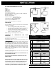
EXHAUST
AIR INLET
RODENT
GUARD
TRIM
COLLAR
VENTILATED
CRAWL SPACE
IN
S
TALLATI
O
N
6
FIGURE 4
Rear view
FIGURE 5
Fresh air supply
FIGURE 6
Fresh air su
pp
l
y