ENERZONE WOOD STOVE MANUAL MODEL SOLUTION 3.4 US ENVIRONMENTAL PROTECTION AGENCY PHASE II CERTIFIED WOOD STOVE STOVE BUILDER INTERNATIONAL INC.. 1700, Leon-Harmel, Quebec City (Quebec), Canada G1N 4R9 Tel : (418) 527-3060 Fax : (418) 527-4311 www.enerzone-intl.
INTRODUCTION Stove Builder International, one of the most important wood stove and fireplace manufacturers in North America, congratulates you on your purchase and wishes to help you get maximum satisfaction from your wood stove. In the pages that follow, we will give you advice on wood heating and controlled combustion as well as technical specifications regarding installation, operation and maintenance of the model you have chosen.
TABLE OF CONTENTS 1.1 GENERAL INSTALLATION ....................................................................................................... 4 1.1.1 Installation of the decorative u-shaped inserts .................................................................... 5 1.1.2 Door overlay installation ..................................................................................................... 5 1.2 POSITIONING THE STOVE ...........................................................................
SECTION 5.0 SPECIFICATIONS .......................................................................................................... 38 5.1 SOLUTION 3.4 ............................................................................................................................ 38 ENERZONE LIMITED LIFETIME WARRANTY ..............................................................................
SECTION 1.0 - INSTALLATION When installed and operated as described in these instructions, the E.P.A Enerzone wood stove is suitable for use as a freestanding wood stove in residential installations. The E.P.A Enerzone wood stove is not intended for installation in a bedroom. In Canada, the CSA B365 Installation Code for Solid Fuel Burning Appliances and Equipment and the CSA C22.1 Canadian National Electrical Code are to be followed in the absence of local code requirements.
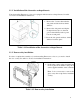
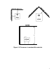
1.1.1 Installation of the decorative u-shaped inserts Your freestanding Enerzone wood stove is equipped with decorative u-shaped inserts. See table 1.1.2 below for installation instructions : 1- Remove the 7 screws that retain the side panels and the rear heat shield deflector. 2- Remove the side panels and clip the U-shaped inserts (choose between gold or nickel finish) at the top and bottom of each panel. 3- Screw the side panels and heat shield deflector back into place. Table 1.1.
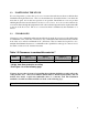
1.2 POSITIONING THE STOVE It is very important to position the wood stove in an area that will favour the most efficient heat distribution throughout the house. The stove should therefore be installed in the room where the most time is spent, and in the most spacious room possible. Recall that wood stoves produce radiating heat, the heat we feel when we are close to a wood stove.
Figure 1.
1.3.1 Reduced clearances You may decrease the clearances by installing heat radiation shields between the walls or the ceiling and the stove. These heat radiation shields must be installed permanently, and can include sheet metal, a rigid non-combustible sheet or a masonry wall.
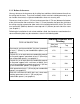
Graphic 1 A- Clearance to combustible material with no protection. B- 500 mm (20 po.) minimum; C- 25 mm (1 po.) minimum; D- Between 25 mm (1 po.) and 75 mm (3 po.) ; E- 75 mm (3 po.) minimum; F- 458 mm (18 po.) minimum. 1- Wall shielding ; 2- Non-combustible spacers ; 3- Ceiling shielding ; 4- Combustible wall ; 5- Ceiling; 6- Heater (side view) ; 7- Heater (top view).
Graphic 2 A- 25 mm (1 po.) minimum; 1- Combustible wall ; 2- Non-combustible spacer; 3- 0.61 mm (0.024") sheet metal. Graphic 3 A- 25 mm (1 po.) minimum; 1- Combustible wall; 2- Non-combustible spacer; 3- Fire-proof support; 4- Ceramic tile or equivalent non-combustible material. _____________________________________________________________________________ Graphic 4 A- 25 mm (1 po.) minimum; 1- Combustible wall; 2- Non-combustible spacer; 3- 0.61 mm (0.
Graphic 5 A- 25 mm (1 po.) minimum; 1- Combustible wall; 2- Non-combustible spacer; 3- Brick. Graphic 6 A- 25 mm (1 po.) minimum; 1- Combustible wall; 2- Non-combustible spacer; 3- 0.61 mm (0.024") sheet metal; 4- Brick.
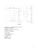
1.4 FLOOR PROTECTOR If the stove is to be installed on top of a combustible floor, it must be guarded by a non-combustible material extending at least 18” (458mm) from the front and 8” (200mm) from the sides and the back of the firebox., as shown in Figure 1.4 below. Please refer to local building codes for suitable floor protection materials. FRONT SIDES BACK 18” (458 mm) 8” (200 mm) 8” (200 mm) Canada Canada Canada 16" (406mm) 8" (200mm) 8" (200mm) USA USA USA FIGURE 1.
SECTION 2.0 CHIMNEY (FLUE SYSTEM) 2.1 DEFINITIONS For clarity, the following definitions should be used with respect to these instructions: • A chimney system consists of a connector off the top of the stove, and a chimney, which attaches to the connector and terminates outside the house. • A chimney can be a masonry chimney (of masonry construction with an inside liner), or a factory built chimney.
USA the ANSI NFPA 70 and ANSI NFPA 211 installation codes are to be followed. If you are using a masonry chimney, it is important that it be built in compliance with the specifications of the Building Code. It must be lined with fire clay bricks, or clay tiles, sealed together with fire cement, or have a listed solid fuel burning stainless steel liner. Round chimneys are the most efficient. The interior diameter of the chimney should be identical to the stove's smoke exhaust.
FIGURE 2.2 Minimum Height of the Chimney 2.2.1 Step by step installation of your factory-built chimney The way to install your chimney may vary from one chimney manufacturer to another. For installation instructions, we advise you to consult your chimney manufacturer whose products are sold at many North American retailers of wood stoves and related heating accessories.
Stove pipe • An adequate number of stove pipe sections. • A 90o elbow FIGURE 2.2.
Typical installation through the ceiling Ceiling support system If your chimney must rise inside the house and go through the ceiling, you need to connect it to your stove at the ceiling level.
2.2.2 Typical installation through an existing masonry chimney You can also install your stove using your existing masonry chimney. To do so, follow the guidelines below. You may want to use a factory-built thimble, on construct your own brick thimble. If you are using a masonry chimney, it is important that it be built in compliance with the specifications of the Building Code in your region. It must normally be lined with fire clay bricks, metal or clay tiles sealed together with fire cement.
FIGURE 2.2.
FIGURE 2.2.
2.3 CHIMNEY CONNECTOR Your chimney connector (commonly called stove pipe) and chimney must have the same diameter as the stove’s exhaust outlet. The stove pipe must be made of aluminized or cold roll steel with a minimum 24-gauge thickness (0.021" or 0.53 mm). It is strictly forbidden to use galvanized steel.
FIGURE 2.3 (A) Connecting Sections 1/4" RISE PER FOOT FIGURE 2.
Avoid 90 degree eblows We recommend that you use two 45 degree elbows instead 23
2.4 DRAFT Your E.P.A Enerzone stove’s performance will be optimised if it is installed with a chimney (flue) system that provides an adequate draft. The draft is the force that moves air from the appliance up through the chimney and is predominantly affected by the height and diameter of the chimney, as well as the stack temperatures of the stove. If you test the draft using a pressure gauge, the reading should be between .05 - .07 inches of water column (w.c.) at a medium-high fire.
2.6 THE ADVANTAGE OF USING A BLOWER (FAN) A blower is installed at the back of your E.P.A Enerzone stove model Solution 3.4. The blower should be used if you wish to redistribute into a room the heat trapped at the back of your stove. By forcing hot air toward the front, the blower enables you to extend the radiation and convection power of your stove.
SECTION 3.0 OPERATION Keep these instructions for future reference. WARNING: • ANY MODIFICATION OF THE APPLIANCE THAT HAS NOT BEEN APPROVED IN WRITING BY THE TESTING AUTHORITY IS CONSIDERED AS BREACHING CSA B365 (CANADA), AND ANSI NFPA 211 (USA). • • DO NOT USE FLAMMABLE LIQUIDS OR AEROSOLS TO START OR REKINDLE THE FIRE. DO NOT USE FLAMMABLE LIQUIDS OR AEROSOLS IN THE VICINITY OF THIS APPLIANCE WHEN IT IS OPERATING. • DO NOT STORE FUEL WITHIN HEATER INSTALLATION CLEARANCES.
3.1 SAFETY INFORMATION • These stoves are designed for safe operation WHEN BURNING WOOD ONLY. Altering or modifying the unit or installation without proper authorisation will void the certification, warranty, and safety listing, and may result in a safety hazard. • For safety reasons, never leave the unit unattended with the door open or ajar.
3.2 • Although the ceramic glass is extremely durable under any normal use, a few precautions are required. Do not attempt to push logs further into the fire by using the door, as the glass may break if any solid object heavily contacts it. • Never operate the stove with the door open, or cracked slightly open, except briefly during the lighting operation, and during refuelling. Leaving the door open continuously could seriously overheat the chimney and adjacent combustibles.
Energy yield (millions of BTU/cord) Oak 29 Sugar Maple 28 Beech 26 High energy yield Yellow birch 25 Ash 24 Elm 23 Larch (Tamarack) 23 Red Maple 23 Douglas red fir 23 Medium energy yield Silver birch 22 Alder 18 Poplar 17 Hemlock 17 Spruce 17 Pine 17 Low energy yield Bass 16 Fir 13 Data provided by Energy, Mines and Resources – Canada Wood species TABLE 3.2 Energy yield for wood species 3.2.1 The use of manufactured logs There are numerous types of manufactured logs sold on the market.
3.2.2 Simple wood moisture test Add one large piece of wood to the top of an established fire. If it starts to burn on three sides within one minute, it is dry and seasoned and right for burning. If it turns black and starts to burn in about three minutes or more, it is damp. If it turns black and does not start burning until five minutes or more, it is green and wet. If it hisses at any time, the wood is soaked and will not burn until the excess of moisture is boiled away. 3.
Intensity Low Medium Low Medium High High Draft Setting Push Control completely to end of travel toward the left. Pull Control to the right by 3/8” from closed position. Pull Control by 3/4” to the right from closed position. Pull Control completely to end of travel toward the right. Table 3.4 Closing the draft control down too soon will lower combustion efficiency, and may result in creosote build-up in the chimney (which could lead to a future chimney fire).
long enough to achieve a hot fire. The wood should be placed with air in between individual pieces. Use a poker to make an air channel in the embers below the wood. This will allow air to flow under the wood for a more efficient burn. In order to achieve an optimum efficiency from your unit, we suggest that you operate it with the air control completely closed. Make sure that you have a good fire going and an adequate ember bed before you completely close the air control.
SECTION 4.0 4.1 MAINTENANCE CLEANING AND PAINTING YOUR STOVE Clean the stove frequently so that soot, ash, and creosote do not accumulate. Do not attempt to clean the stove when the unit is hot. Special care must be taken with plated surfaces in order to maintain the finish at its original brilliance. Do not use an abrasive cleaner which will scratch the paint or plated finish. Use only a soft and clean damp cloth.
Glass specifications: Robax 5mm with dimensions of 17 3/32" x 9 13/16" GLASS FRAME GLASS GLASS RETAINER DOOR FRAME DOOR OVERLAY 4.3 GASKETING It is recommended that you change the door gasket (which makes your stove door air tight) once a year, in order to insure good control over the combustion, maximum efficiency and security. To change the door gasket, simply remove the damaged one.
• Push the ashes through the hole and leave an ash bed of approximately 1” deep on the firebox bottom to help maintain a hot ember bed. • Clear the ashes from the area where the ash dump plug normally sits so that it will properly seat against the opening edges. Tap it down with your poker to ensure proper seating. • Ashes should be placed in a metal container with a tightly fitting lid.
4.6 4.6.1 BAFFLE INSTALLATION Baffle installation and brick layout for Solution 3.4 model All firebrick and ceramic wool baffles must be properly in place for correct burning operation. Have any damaged firebricks replaced. Check the firebricks annually for damage and replace if they are broken or damaged.
4.7 SECONDARY AIR TUBE REPLACEMENT (see Figure 4.11) Figure 4.7.
SECTION 5.0 SPECIFICATIONS 5.1 SOLUTION 3.4 Fuel Type Cordwood Test Standards ULC S627 (CSA B366.2) & UL 1482 residential. Maximum recommended heating area : 500 to 2,700 square feet Heating capacity* – BTU/hr., EPA test wood : 60,200 Heating capacity* – BTU/hr.
ENERZONE LIMITED LIFETIME WARRANTY The warranty of the manufacturer extends only to the original consumer purchaser and is not transferable. This warranty covers brand new products only, which have not been altered, modified nor repaired since shipment from factory. Products covered under this warranty must have been manufactured after the revision date indicated below.