INSTALLATION AND OPERATION MANUAL Solution 3.4 US ENVIRONMENTAL PROTECTION AGENCY PHASE II CERTIFIED WOOD STOVE Safety tested according to ULC S627 and UL 1482 Standards by Intertek Testing Services www.enerzone-intl.com Stove Builder International Inc. 250, rue de Copenhague, St-Augustin-de-Desmoures (Quebec) Canada G3A 2H3 Tel: (418) 878-3040 Fax: (418) 878-3001 READ AND KEEP THIS MANUAL FOR REFERENCE This manual is available for free download on the manufacturer’s web site.
THANK YOU FOR CHOOSING THIS ENERZONE WOOD STOVE As one of North America’s largest and most respected wood stove and fireplace manufacturers, Stove Builder International takes pride in the quality and performance of all its products. We want to help you get maximum satisfaction as you use this product.
Table of content PART A - OPERATION AND MAINTENANCE ...............................6 1 Safety Information .....................................................................6 1.1 Summary of Operation and Maintenance Cautions and Warnings .................................... 6 2 General Information ...................................................................7 2.1 2.2 2.3 2.4 2.4.1 Solution 3.4 Specifications .........................................................................................
5 Maintaining Your Wood Heating System ...............................20 5.1 Stove Maintenance ......................................................................................................... 20 5.1.1 Plated Finish Maintenance........................................................................................... 20 5.1.2 Cleaning Door Glass.................................................................................................... 21 5.1.3 Door adjustment ...............................
Appendix 1: Installing the Optional Door Overlay .....................40 Appendix 2: Installing Trims ........................................................41 Appendix 3: Installation and Use of Air Circulation Fan and Thermodisc ...............................................................42 Appendix 4: Installation of Secondary Air Tubes and Baffle ...44 Appendix 5: Exploded Diagram and Parts List ..........................49 ENERZONE LIMITED LIFETIME WARRANTY .............................
PART A - OPERATION AND MAINTENANCE Please see Part B for installation instructions. 1 Safety Information 1.1 Summary of Operation and Maintenance Cautions and Warnings • HOT WHILE IN OPERATION, KEEP CHILDREN, CLOTHING AND FURNITURE AWAY. CONTACT MAY CAUSE SKIN BURNS. GLOVES MAY BE NEEDED FOR STOVE OPERATION. • USING A STOVE WITH CRACKED OR BROKEN COMPONENTS, SUCH AS GLASS OR FIREBRICKS OR BAFFLES MAY PRODUCE AN UNSAFE CONDITION AND MAY DAMAGE THE STOVE.
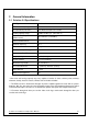
2 General Information 2.1 Solution 3.4 Specifications Fuel Type Cordwood Test Standards (safety) ULC S627 and UL 1482 Test Standard (emissions) EPA Method 28 (40 CFR Part 60) Heating capacity range* 1,000 to 2,700 sq. ft. (93 to 251 m2) Maximum heat output** (EPA test fuel) Maximum heat output** (natural hardwood fuel) 60,175 BTU/h (17.64 kW/h) 100,000 BTU/h (29.31 kW/h) Optimum efficiency 78 % Particulate Emissions 3.9 g/h Test Standard (efficiency) CSA B415.
Solution 3.
2.2 Zone Heating and How to Make it Work for You Your new Solution 3.4 wood stove is a space heater, which means it is intended to heat the area it is installed in, as well as spaces that connect to that area, although to a lower temperature. This is called zone heating and it is an increasingly popular way to heat homes or spaces within homes.
The emission control and advanced combustion features of your stove can only work properly if your fuel is in the correct moisture content range of 15 to 20 percent. See Section 3 of this manual for suggestions on preparing fuelwood and judging its moisture. 2.4 The SBI Commitment to You and the Environment The SBI team are committed to protecting the environment, so we do everything we can to use only materials in our products that will have no lasting negative impact on the environment. 2.4.
3 Fuel 3.1 Materials That Should Not be Burned • GARBAGE OF ANY KIND, • COAL OR CHARCOAL, • TREATED, PAINTED OR COATED WOOD, • PLYWOOD OR PARTICLE BOARD, • FINE PAPER, COLORED PAPER OR CARDBOARD, • SALT WATER DRIFTWOOD • MANUFACTURED LOGS CONTAINING WAX OR CHEMICAL ADDITIVES • RAILROAD TIES • LIQUIDS SUCH AS KEROSCENE OR DIESEL FUEL TO START A FIRE 3.2 How to Prepare or Buy Good Firewood 3.2.
3.2.3 Log Length Logs should be cut about 1” (25 mm) shorter than the firebox so they fit in easily. Pieces that are even slightly too long make loading the stove very difficult. The most common standard length of firewood is 16” (400 mm). The pieces should be a consistent length, with a maximum of 1” (25 mm) variation from piece to piece. 3.2.4 Piece Size Firewood dries more quickly when it is split. Large unsplit rounds can take years to dry enough to burn.
3.2.5 How to Dry Firewood Firewood that is not dry enough to burn is the cause of most complaints about wood inserts. Continually burning green or unseasoned wood produces more creosote and involves lack of heat and dirty glass door. See Section 5: Maintaining your wood heating system for concerns about creosote.
You could buy a wood moisture meter to test your firewood. 3.3 Manufactured Logs Do not burn manufactured logs made of wax impregnated sawdust or logs with any chemical additives. Manufactured logs made of 100% compressed sawdust can be burned, but be careful burning too much of these logs at the same time. Start with one manufactured log and see how the stove reacts.
Burn one or two small fires to begin the curing and conditioning process. Then build bigger and hotter fires until there is no longer any paint smell from the stove. Once the paint smell disappears, your stove is ready for serious heating. 4.2 Lighting Fires Each person who heats with wood develops their own favorite way to light fires. Whatever method you choose, your goal should be to get a hot fire burning quickly. A fire that starts fast produces less smoke and deposits less creosote in the chimney.
Start by placing three or four full-sized split pieces of dry firewood in the firebox. Next, place 4 or 5 more finely split pieces of firewood (2” to 3” [50 mm to 75 mm] in dia.) on the base logs at right angles (log cabin style). Now place about 10 pieces of finely split kindling on the second layer at right angles. The fire is topped with about 5 sheets of newspaper. You can just bunch them up and stuff them in between the kindling and the underside of the baffle.
wood should provide several hours of heating. The size of each load can be matched to the amount of heat needed. When you burn in cycles, you rarely need to open the stove’s loading door while the wood is flaming. This is an advantage because there is more chance that smoke will leak from the stove when the door is opened as a full fire is burning. This is especially true if the chimney connector has 90 degree elbows and if the chimney runs up the outside wall of the house.
4.3.4 Firing Each New Load Hot Place the new load of wood on and behind the charcoal, and not too close to the glass. Close the door and open the air control fully. Leave the air control fully open until the firebox is full of flames, the wood has charred to black and its edges are glowing red.
4.3.6 Building Different Fires for Different Needs Using the air control is not the only way to match the stove’s heat output to the heat demand. Your house will need far less heat in October than in January to be kept at a comfortable temperature. If you fill the firebox full in fall weather, you will either overheat the space or turn the stove down so much that the fire will be smoky and inefficient. Here are some suggestions for building fires to match different heat demand. 4.3.6.
The table below provides a very general indication of the maximum burn cycle times you are likely to experience, based on firebox volume. FIREBOX VOLUME MAXIMUM BURN TIME <1.5 cubic feet 3 to 5 hours 1.5 c.f. to 2.0 c.f 5 to 6 hours 2.0 c.f. to 2.5 c.f. 6 to 8 hours 2.5 c.f. to 3.0 c.f. 8 to 9 hours >3.0 c.f. 9 to 10 hours Long burn times are not necessarily an indication of efficient stove operation.
5.1.2 Cleaning Door Glass Under normal conditions, your door glass should stay relatively clear. If your firewood is dry enough and you follow the operating instructions in this manual, a whitish, dusty deposit will form on the inside of the glass after a week or so of use. This is normal and can be easily removed when the stove is cool by wiping with a damp cloth or paper towel and then drying. Never try to clean the glass when the stove is hot.
5.1.3 Door adjustment In order for your stove to burn at its best efficiency, the door must provide a perfect seal with the firebox. Therefore, the gasket should be inspected periodically making sure to obtain an air tight fit. Airtightness can be improved with a simple latch mechanism adjustment. To increase the pressure on the gasket, remove one washer (A). To reduce pressure on the door, when putting a new door gasket for example, put two washers. To adjust: 1. Unscrew the nut. 2.
5.1.4 Replacing the Door Gasket It is important to maintain the gasket in good condition. After a year or more of use, the door gasket will compress and become hard, which may allow air to leak past it. You can test the condition of the door gasket by closing and latching the door on a strip of paper. Test all around the door. If the paper slips out easily anywhere, it is time to replace the gasket. Use the correct replacement gasket that you can purchase from your retailer.
Do not abuse the glass door by striking or slamming shut. Do not use the stove if the glass is broken. To change the glass, perform the same operation described above. 5.1.6 Cleaning and Painting the Stove Do not attempt to clean or paint the stove when the unit is hot. Painted surfaces can be wiped down with a damp cloth. Plated surfaces may be scratched by abrasive cleaners. To maintain the finish at its original brilliance, use only a damp soft cloth to clean plated surfaces.
Contact your local municipal or provincial fire authority for information on how to handle a chimney fire. Have a clearly understood plan to handle a chimney fire. 5.2.3 Cleaning the Chimney Chimney cleaning can be a difficult and dangerous job. If you don’t have experience cleaning chimneys, you might want to hire a professional chimney sweep to clean and inspect the system for the first time. After having seen the cleaning process, you can decide if it is a job you would like to take on.
PART B - INSTALLATION 6 Safety Information 6.1 Summary of Installation Cautions and Warnings • THE INFORMATION GIVEN ON THE CERTIFICATION LABEL AFFIXED TO THE APPLIANCE ALWAYS OVERRIDES THE INFORMATION PUBLISHED, IN ANY OTHER MEDIA (OWNER’S MANUAL, CATALOGUES, FLYERS, MAGAZINES AND/OR WEB SITES). • MIXING OF APPLIANCE COMPONENTS FROM DIFFERENT SOURCES OR MODIFYING COMPONENTS MAY RESULT IN HAZARDOUS CONDTIONS. WHERE ANY SUCH CHANGES ARE PLANNED, STOVE BUILDER INTERNATIONAL INC.
7 Clearances to Combustible Material The clearances shown in this section have been determined by test according to procedures set out in safety standards ULC S627 (Canada) and UL1482 (U.S.A.). When the stove is installed so that its surfaces are at or beyond the minimum clearances specified, combustible surfaces will not overheat under normal and even abnormal operating conditions. No part of the stove or flue pipe may be located closer to combustibles than the minimum clearances given below. 7.
Clearances to combustible materials and floor protection 28 Solution 3.
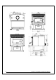
7.3 Floor protector Your stove has been conceived to prevent the floor from overheating. However, it must be placed on a noncombustible surface to protect the floor from hot embers that could fall from the stove while loading or cleaning. There are differences between floor protections in Canada and in the United States, as it is illustrated in the table below and on the figure Clearances to combustible materials and floor protection.
7.4 Reducing Wall and Ceiling Clearances Safely It is often desirable to reduce the minimum installation clearances by placing the stove closer to walls so the installation takes up less floor space. You can safely reduce the minimum clearances by permanently installing a shield between the stove and combustible material. The rules for safe shields can be complicated, so read them carefully and follow them exactly.
Clearances for shield construction Solution 3.
7.4.2 Table of Clearance Reduction Percentages Clearances may be reduced by these percentages Sides and rear % Type of shield Top % (ceiling) Can/USA (%) USA min. Can/USA (%) USA min. 67 12 po 50 18 po Ceramic tiles, or equivalent noncombustible material, on noncombustible board spaced out at least 25 mm (1 in)* by non-combustible spacers 50 18 po 33 24 po Ceramic tiles, or equivalent noncombustible material, on noncombustible board, with a minimum of 24 gauge (0.
8 The Venting System 8.1 General The venting system, made up of the chimney and the connecting pipe between the stove and the chimney, acts as the engine that drives your wood heating system. Even the best stove will not function safely and efficiently as intended if it is not connected to a suitable chimney. The heat in the flue gases that pass from the stove and chimney connector into the chimney is not waste heat.
8.2.2 Masonry Chimneys The stove may also be connected to a masonry chimney, provided the chimney complies with the construction rules found in the building code enforced locally. The chimney must have either a clay liner or a suitably listed stainless steel liner. If the masonry chimney has a square or rectangular liner that is larger in cross sectional area than a round 6” flue, it should be relined with a suitably listed 6” stainless steel liner.
8.4 The Relationship Between the Chimney and the House Because the venting system is the engine that drives the wood heating system, it must have the right characteristics. The signs of bad system design are cold backdrafting when there is no fire in the stove, slow kindling of new fires, and smoke roll-out when the door is opened for loading. There are two guidelines to follow. First, the chimney should be installed up through the heated space of the house, not out and up an outside wall.
8.4.2 Why the chimney should penetrate the highest heated space When it is cold outside, the warm air in the house is buoyant so it tends to rise. This tendency of warm air to rise creates a slight pressure difference in the house. Called ‘stack effect’, it produces a slightly negative pressure low in the house (relative to outside) and a slightly positive pressure zone high in the house.
8.5 Supply of Combustion Air In Canada, wood stoves are not required to have a supply of combustion air from outdoors (except in mobile homes) because research has shown that these supplies do not give protection against house depressurization and may fail to supply combustion air during windy weather. However, to protect against the risk of smoke spillage due to house depressurization, a carbon monoxide (CO) detector/alarm is required in the room where the stove is installed.
Use 45 degree elbows where possible, instead of 90 degree elbows. 38 Solution 3.
The rules below are based on those found in the CSA B365 installation code. Please carefully follow these installation instruction rules, or those enforced where you live. • • • • • • • • • • • • • • • • Maximum overall length of straight pipe: 3 m (10 ft.) including elbows. Minimum clearance from combustible material: 450 mm (18 in.). The minimum clearance may be reduced by 50 percent to 225 mm (9 in.) if suitable shielding is installed either on the pipe or on the combustible surface.
Appendix 1: Installing the Optional Door Overlay In order to complete the assembly of your wood stove, you need to install the door overlay. See figure below for installation instructions: Position the overlay (A) on the door frame and secure it from the inside of the door using the 4 included screws (B). To facilitate the installation, do not tighten the screws until they are all installed. Note: It is not necessary to remove the glass or any other component to install the overlay 40 Solution 3.
Appendix 2: Installing Trims Your freestanding Enerzone wood stove is equipped with decorative u-shaped trims. See installation instructions below: 1- Remove the 6 screws (A) that secure both decorative side panels (B). 2- Slide the panels towards the front to release them from the front brackets. 3- Choose between the gold or nickel “U” shaped decorative trims (C) and remove the protection film before installation.
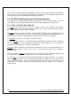
Appendix 3: Installation and Use of Air Circulation Fan and Thermodisc A fan is installed on the back of the stove to increase the flow of air past heat exchange surfaces and to help circulate warm air in the room. When used regularly, the fan can provide a small increase in efficiency, up to 2 percent. However, the use of a fan should not be used as a way to gain more output from a stove that is undersized for the space it is intended to heat.
CAUTION: ENSURE THAT THE FAN’S POWER CORD IS NOT IN CONTACT WITH ANY SURFACE OF THE STOVE TO PREVENT ELECTRICAL SHOCK OR FIRE DAMAGE. DO NOT RUN THE POWER CORD BENEATH THE STOVE. Solution 3.
Appendix 4: Installation of Secondary Air Tubes and Baffle 1- Remove the 4 bricks on the left hand side of the combustion chamber. 2- Starting with the rear tube, lean and insert the right end of the secondary air tube into the rear right channel hole. Then lift and insert the left end of the tube into the rear left channel. 3- Align the notch in the left end of the tube with the left air channel hole. Secure the tube in the channel hole using a cotter pin.
Note that secondary air tubes (A) can be replaced without removing the baffle board (B). Important Notes: The air tubes are identified for placement as follows: Model Type of tube Solution 3.4 Front ► 28 holes of 0.203" Middle► 28 holes of 0.172’’ Rear ► 28 holes of 0.172’’ Solution 3.
Baffle installation and brick layout All firebricks, baffles and ceramic wool insulation must be properly in place for optimum burning efficiency. Have any damaged firebrick, baffle and or insulation replaced. Step 1: Start by taking out the four firebricks on the left hand side of the firebox then remove the cotter pins and the secondary air tubes from the stove making sure to identify them so they can be reinstalled in the same location. 46 Solution 3.
Step 2: Put a piece of ceramic wool insulation on top of the first baffle the notch facing down (as per the right hand side image), insert the two parts into the stove and over the right and left secondary air channel. Then push the baffle and its insulation against the firebox’s back wall. Step 3: Repeat step 2 for the second baffle and insulation. Solution 3.
Step 4: Reinstall the secondary air tubes and cotter pins in their original location and put the four left hand side firebricks back into place. 48 Solution 3.
Appendix 5: Exploded Diagram and Parts List Solution 3.
IMPORTANT: THIS IS DATED INFORMATION. When requesting service or replacement parts for your stove, please provide the model number and the serial number. We reserve the right to change parts due to technology upgrade or availability. Contact an authorized dealer to obtain any of these parts. Never use substitute materials. Use of non-approved parts can result in poor performance and safety hazards.
# Item Description 33 SE57040 AIR CONTROL DAMPER 1 34 AC03095 130 CFM BLOWER WITH VARIABLE SPEED CONTROL 1 35 60013 POWER CORD 96" X 18-3 type SJT 1 36 44070 CROSSFLOW BLOWER 115V-60Hz-56W (B) 1 37 44080 RHEOSTAT WITH NUT 1 38 44087 RHEOSTAT NUT 1 39 44085 RHEOSTAT KNOB 1 40 AC02055 QUICK CONNECT THERMODISC 1 41 24096 ROUND CAST IRON ASH PLUG 1 42 PL36048 4" X 4" X 1 1/4'' REFRACTORY BRICK 1 43 29020 4 1/2'' X 9'' X 1 1/4'' REFRACTORY BRICK HD 17 44 29005 6"
ENERZONE LIMITED LIFETIME WARRANTY The warranty of the manufacturer extends only to the original consumer purchaser and is not transferable. This warranty covers brand new products only, which have not been altered, modified nor repaired since shipment from factory. Products covered under this warranty must have been manufactured after the revision date indicated below.