802.11a/b/g Outdoor Dual Radio Concurrent AP/Bridge/Repeater EOA7530 User Manual Version : 1.
Table of Contents CHAPTER 1 PRODUCT OVERVIEW ..................................................................................................................................4 1.1 FEATURES ................................................................................................................................................................. 4 1.2 BENEFITS ..............................................................................................................................................
5.6.1 Advanced Settings (Access Point).................................................................................................................... 44 5.6.2 Advanced Settings (Client Bridge / Client Router) ........................................................................................... 45 5.7 WIRELESS ACCESS CONTROL LIST ...................................................................................................................................... 46 CHAPTER 6 LAN SETUP.............
APPENDIX A – SPECIFICATIONS.................................................................................................................................... 72 APPENDIX B – TROUBLESHOOTING.............................................................................................................................. 75 B.1 PROBLEM SOLVING ......................................................................................................................................................... 75 B.
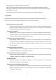
Chapter 1 Product Overview Thank you for choosing the EOA7530. The EOA7530 is a dual‐radio wireless outdoor Access Point/Client/Bridge designed as an enterprise‐scale product to deliver unparalleled range and performance on both 2.4 GHz and 5 GHz wireless local‐area networks (WLANs). With certified IP‐65 protection, the EOA7530 is designed to deliver high reliability whether installed indoors or outdoors. The EOA7530 is actually three devices in one: an Access Point, a Client Bridge, and a Client Router.
‐ ‐ ‐ ‐ Collocates with any antenna in your environment Web‐based Configurator lets administrators configure and manage the EOA7530 remotely Watertight, weatherproof enclosure prevents interior damage from water and exterior damage from weather corrosion Comes with a wall‐mount and mast mounting kit support to simplify installation 1.2 Benefits The EOA7530 is the ideal product around which you can build your WLAN.
1.3 Package Contents Open the package carefully and make sure it contains all of the items listed below. ‐ One EnGenius Concurrent Dual Radio Wireless Outdoor Access Point / Client Bridge (EOA7530) ‐ One PoE injector 48V/0.375A Power Adapter ‐ One mounting kit ‐ One grounding cable ‐ One quick‐installation guide ‐ One CD containing the user manual ‐ Two N‐Type Dual Band Omni directional Antenna If any item is missing or damaged, contact your place of purchase immediately.
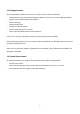
Chapter 2 Hardware Overview The following figures show the key components on the EOA7530. 2.1 Bottom View The bottom panel of the EOA7530 contains an RJ‐45 port and a Reset button. ‐ The RJ‐45 port connects to an Ethernet adapter in a computer you use to configure the EOA7530. For more information, see Chapter 4. ‐ The Reset button can be used to reboot the EOA7530 and return the device to its default factory configuration, erasing any overrides you may have made to the device’s default settings.
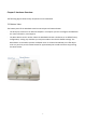
2.2 Back Panel The back panel of the EOA7530 contains the connectors for attaching 5 GHz and 2.4 GHz antennas and the RSSI signal indicators.
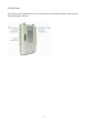
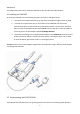
3 Installation This chapter describes how to install the EOA7530. It also describes the EOA7530 LEDs. 3.1 Installing the EOA7530 To install the EOA7530, use the following procedure and refer to the figure below. 1. Connect the two dipole antennas to the top of the EOA7530 and tighten them by hand. 2. Unscrew the compartment door on the bottom of the EOA7530 and remove the compartment door to expose the RJ‐45 jack and Reset switch.
the EOA7530 LEDs. LED Color Mode Status Power Green OFF= EOA7530 is not receiving power. ON= EOA7530 is receiving power. LAN Green OFF = EOA7530 is not connected to the network. ON = EOA7530 is connected to the network, but not sending or receiving data. Blink = EOA7530 is sending or receiving data. WLAN1 802.11a Green Access Point OFF = EOA7530 radio is off and the device is not or Client sending or receiving data.
Chapter 3 Configuring Your Computer for TCP/IP To configure the EOA7530, use the instructions in the appropriate section of this chapter to configure the TCP/IP settings on a computer that will be used to configure the EOA7530.
3.1 Configuring Microsoft Windows 7 Use the following procedure to configure a computer running Microsoft Windows 7. 1. In the Start menu search box, type: ncpa.cpl 2. When the Network Connections List appears, right‐click the Local Area Connection icon and click Properties. 3. In the Networking tab, click either Internet Protocol Version 4 (TCP/IPv4) or Internet Protocol Version 6 (TCP/IPv6), and then click Properties.
4. In the properties dialog box, click Obtain an IP address automatically to configure your computer for DHCP.
5. Click the OK button to save your changes and close the dialog box. 6. Click the OK button again to save your changes. 3.2 Configuring Microsoft Windows Vista Use the following procedure to configure a computer running Microsoft Windows Vista with the default interface. If you use the Classic interface, where the icons and menus resemble previous Windows versions, perform the procedure in section 4.4. 1.
6. In the Internet Protocol Version 4 Properties dialog box, click Obtain an IP address automatically to configure your computer for DHCP. 7. Click the OK button to save your changes and close the dialog box. 8. Click the OK button again to save your changes.
3.3 Configuring Microsoft Windows XP Use the following procedure to configure a computer running Microsoft Windows XP with the default interface. If you use the Classic interface, where the icons and menus resemble previous Windows versions, perform the procedure in section 4.4. 1. On the Windows taskbar, click Start, click Control Panel, and then click Network and Internet Connections. 2. Click the Network Connections icon. 3.
5. In the Local Area Connection Properties dialog box, verify that Internet Protocol (TCP/IP) is checked. Then select Internet Protocol (TCP/IP) and click the Properties button. The Internet Protocol (TCP/IP) Properties dialog box appears. 6. In the Internet Protocol (TCP/IP) Properties dialog box, click Obtain an IP address automatically to configure your computer for DHCP. Click the OK button to save this change and close the Internet Protocol (TCP/IP) Properties dialog box. 7.
4. In the Local Area Connection Status dialog box, click the Properties button. The Local Area Connection Properties dialog box appears. 5. In the Local Area Connection Properties dialog box, verify that Internet Protocol (TCP/IP) is checked. Then select Internet Protocol (TCP/IP) and click the Properties button. 6. Click Obtain an IP address automatically to configure your computer for DHCP. 7. Click the OK button to save this change and close the Local Area Connection Properties dialog box. 8.
3.5 Configuring an Apple Macintosh Computer The following procedure describes how to configure TCP/IP on an Apple Macintosh running Mac OS 10.2. If your Apple Macintosh is running Mac OS 7.x or later, the steps you perform and the screens you see may differ slightly from the following. However, you should still be able to use this procedure as a guide to configuring your Apple Macintosh for TCP/IP. 1. Pull down the Apple Menu, click System Preferences, and select Network. 2.
Chapter 4 Introducing the Web Configurator The EOA7530 has a built‐in Web Configurator that lets you manage the unit from any location using a Web browser that supports HTTP and has JavaScript installed. 4.1 Logging in to the Web Configurator After configuring the computer for TCP/IP using the procedure appropriate for your operating system, use that computer’s Web browser to log in to the EOA7530 Web Configurator. 1. Launch your Web browser. 2. In the browser address bar, type 192.168.1.
4.2 Best Practices Perform the following procedures regularly to make the EOA7530 more secure and manage the EOA7530 more effectively. ‐ Change the default password. Use a password that is not easy to guess and that contains different characters, such as numbers and letters. The EOA7530 username cannot be changed. For more information, see page 58. ‐ Back up the configuration and be sure you know how to restore it.
Chapter 5 Wireless Configuration This chapter describes the EOA7530’s wireless settings. 5.1 Selecting Operating Modes The EOA7530 supports three operating modes: Access Point, Client Bridge, and Client Router. Using the procedures in the following sections, you can configure the EOA7530 to use one operating mode for a 2.4 GHz network and another operating mode for 5 GHz networks (see section 5.1.1), or the same operating mode for 2.4 GHz and 5 GHz networks (see section 5.1.2). 5.1.
2. At the top of the page, click Separate Mode. 3. Under Please choose the Operation Mode. (5G), click the operating mode you want to use for the 5 GHz network. 4. Under Please choose the Operation Mode. (2.4G), click the operating mode you want to use for the 2.4 GHz network. Note: Client Bridge Mode and Client Router Mode cannot be used at the same time. 5. Click Apply. 5.1.2 Selecting Dual Mode for 2.4 GHz and 5 GHz Networks The following procedure describes how to select the same operating mode for 2.
3. Under Please choose the Operation Mode, click the operating mode you want to use for the 5 GHz network. 4. If you selected Client Bridge Mode or Client Router Mode in step 3, click a radio under Please choose which Radio is Enabled. If you selected Access Point Mode in step 3, both radios are selected automatically and cannot be changed because both bands can work at the same time. 5. Click Apply.
5.2 Wireless Settings The EOA7530’s wireless settings are located in the Wireless section of the left pane. 5.2.1 Access Point Mode (Dual Mode) The EOA7530 contains both 2.4 GHz 802.11a and 5 GHz 802.11b/g radios, allowing it to support simultaneous 2.4 GHz 11b/g/n and 5 GHz 11a/n wireless connections when configured for Access Point Mode. In this mode, users with a wireless client device within range can connect to the EOA7530 to access the WLAN. Simultaneous transmission on 2.
Radio Click the radio button to enable or disable wireless functions. Enable SSID# The EOA7530 supports four SSIDs. Each SSID can be configured to use a different VLAN tag. ESSID ESSID is the name of your wireless network (WLAN). In an area where more than one WLAN is present, using a different ESSID allows you to separate the traffic. Any device you want to participate in a particular WLAN must use the same ESSID. The default ESSID is EnGenius.
Channel You should not need to change the wireless channel unless you notice interference or are setting up the EOA7530 near another Access Point. Data Rate Shows the available transmit data rate of the WLAN. The data rate affects throughput. If you select a low data rate value, for example, the throughput is reduced but the transmission distance increases. Auto Channel By default, this option is disabled.
5.2.2 Access Point Mode (5 GHz) Radio Select the appropriate radio button to enable or disable the EOA7530’s wireless functions. Enable SSID# The EOA7530 supports four SSIDs. Each SSID can be configured to use a different VLAN tag. ESSID ESSID is the name of your WLAN. In an area where more than one WLAN is present, using a different ESSID allows you to separate the traffic. Any device you want to participate in a particular WLAN must use the same ESSID. The default ESSID is EnGenius.
5.2.3 Access Point Mode (2.4 GHz) Radio Select the appropriate radio button to enable or disable the EOA7530’s wireless functions. Enable SSID# The EOA7530 supports four SSIDs. Each SSID can be configured to use a different VLAN tag. ESSID ESSID is the name of your WLAN. In an area where more than one WLAN is present, using a different ESSID allows you to separate the traffic. Any device you want to participate in a particular WLAN must use the same ESSID. The default ESSID is EnGenius.
5.2.4 Client Bridge Mode/Client Router Mode (Dual Mode) Client Bridge Mode/ Client Router Mode lets you connect two LAN segments via a wireless link as though they are on the same physical network. Since the computers are on the same subnet, broadcasts will reach all machines. As a result, DHCP information generated by the server will reach all client computers as though the clients resided on one physical network. The following figure shows an example of two EOA7530 devices operating in Client Bridge Mode.
ESSID Specify the Access Point SSID if known. Otherwise, use Site Survey to scan for nearby Access Points (see page 36). Preferred BSSID Specify the MAC address of the Access Point with which you want to associate. 5G Wireless Setting Click this radio button to use the 5 GHz network as your default WLAN. 2.4G Wireless Setting Click this radio button to use the 2.4 GHz network as your default WLAN.
ESSID Specify the Access Point SSID if known. Otherwise, use Site Survey to scan for nearby Access Points (see page 36). Preferred BSSID Specify the MAC address of the Access Point with which you want to associate. 5G Wireless Setting Select a standard IEEE 802.11a wireless band you want to use on the 5 GHz network. Apply / Cancel Click Apply to apply the changes or Cancel to discard your changes and return to the previous settings. 5.2.6 Client Bridge Mode/Client Router Mode (2.
5.2.7 WDS Bridge Mode The Management > Operation Mode page has a 5G section that lets you configure the EOA7530 for WDS Bridge Mode. Please Choose the Operation Mode (5G) Select WDS Bridge Mode to configure the ENH200 for WDS Bridge Mode. Apply / Cancel Click Apply to apply the changes or Cancel to discard your changes and return to the previous settings.
In the next screen, manually enter static IP addresses for the two devices. This mode requires the EOA7530’s DHCP server to be turned off, as noted in the table below. This is the default setting. If you change it, please turn off DHCP Server for WDS Bridge Mode. IP Address Specify the IP address of the EOA7530 LAN port. IP Subnet Mask Specify the subnet mask of the EOA7530 LAN port. Default Gateway Specify the default gateway of the EOA7530 LAN port. 802.
Go to the Management > Status page. Under 5GHz WDS, find the Basic Service Set Identifier (BSSID) or MAC address of the devices you want to bridge together. BSSID (WLAN MAC address) MAC address of the devices you want to bridge together. Record the value below: Record BSSID here: ___________________________________________ Go to the 5GHz Wireless > WDS Link page and configure desired 5GHz wireless channel/frequency. Channels Select the desired 5 GHz channel/frequency.
5.4 5.3 Site Survey Use this feature to scan nearby Access Points. No Numbers of Access Points that the site survey has discovered. Select Click the radio button that corresponds to the Access Point with which you want to associate. Channel Channel that the Access Point is using. SSID SSID that the Access Point is broadcasting. BSSID Access Point’s wireless MAC address. Encryption Encryption method that the Access Point is using to secure data over the WLAN.
AP Scan List (5 GHz / 2.4 GHz) This feature can help you select an Access Point channel by scanning nearby Access Points. Refresh Click Refresh to rescan nearby Access Points.
5.5 Wireless Security Settings The Wireless Security Settings section lets you configure the EOA7530’s security settings. We strongly recommend you use WPA2‐PSK AES for your security settings. 5.5.1 WEP (Access Point) ESSID Selection The EOA7530 supports four SSIDs. Each SSID can be configured to use a different type of authentication. Hidden SSID Select Enable or Disable to broadcast or not broadcast the EOA7530’s SSID.
authenticate itself with the Access Point and then try to associate with it. • Shared Key = all wireless stations share the same secret key. Key Length Level of WEP encryption applied to all WEP keys. Choices are 64‐bit and 128‐bit. Key Type Select an input type of either Hex or ASCII. Default Key Specify which of the four WEP keys the EOA7530 uses as its default. Key1 Specify a password for security key index number 1. For security, each typed character is masked by a dot ().
authenticate itself with the Access Point and then try to associate with it. • Shared Key = all wireless stations share the same secret key. Key Length Level of WEP encryption applied to all WEP keys. Choices are 64‐bit and 128‐bit. Key Type Select an input type of either Hex or ASCII. Default Key Specify which of the four WEP keys the EOA7530 uses as its default. Key1 Specify a password for security key index number 1. Key2 Specify a password for security key index number 2.
Pre‐shared Key Type • TKIP = automatic encryption with WPA‐PSK; requires pre‐shared key. • AES = automatic encryption with WPA2‐PSK; requires pre‐shared key. • WPA2 Mixed = uses both TKIP and AES cipher types; requires a pre‐shared key. Select Passphrase or Hex (64 characters) that can be used to automatically generate security keys. Pre‐shared Key Shared secret between the EOA7530 and Access Points and wireless clients. You cannot type special characters in the pre‐shared key.
5.5.5 RADIUS (Access Point Mode Only) Remote Authentication Dial In User Service (RADIUS) authentication is only available when the EOA7530 is configured for Access Point Mode. Use this feature if you have a RADIUS server. WPA(TKIP), WPA2(AES), and WPA2 Mixed encryption types are also supported. The following figure shows an example of a RADIUS configuration, where two EOA7530 devices installed at different locations communicate with each other wirelessly.
ESSID Selection The EOA7530 supports four SSIDs. Each SSID can be configured to use a different type of authentication. Hidden SSID Select Enable or Disable to broadcast or not broadcast the EOA7530’s SSID. Users cannot reconnect automatically or manually to a WLAN that uses a hidden SSID. A WLAN that uses a hidden SSID does not appear in the Microsoft Windows Wireless Network Connection window. WMM Select Enable or Disable to enable or disable the EOA7530’s WMM functions.
5.6 Wireless Advanced Settings If you do not have experience with configuring advanced wireless settings, leave these options at their default settings. Otherwise, any changes you make can affect performance adversely. 5.6.1 Advanced Settings (Access Point) Fragment Threshold Specify the maximum packet size during transmission. If a large number of clients are accessing the WLAN, specify a small value to avoid collisions.
(DTIM). A DTIM is a countdown that informs clients about the next window for listening to broadcast and multicast messages. The default value is 1. Note: The DTIM is a multiple of the Beacon (TIM), so if the DTIM is set to 3, a DTIM message is sent with every third Beacon. Preamble Type Tells the receiver that data is on the way. The preamble allows the receiver to acquire the wireless signal and synchronize itself with the transmitter. Select Long Preamble or Short Preamble.
packet. To ensure communication, use the maximum value. Decreasing this value causes the sending device to discard the current packet and move on to the next. Preamble Type Tells the receiver that data is on the way. The preamble allows the receiver to acquire the wireless signal and synchronize itself with the transmitter. Select Long Preamble or Short Preamble. Long Preamble can provide better wireless LAN compatibility with legacy devices, while Short Preamble can provide better WLAN performance. 802.
MAC Address Filtering Table Check all the conditions you added. Delete Selected Check an option below the Select column and click Delete Selected to delete the option. Delete All Click Delete All to erase all options in the table. Reset Click Reset to discard your selection. Apply / Cancel Click Apply to apply the changes or Cancel to discard your changes and return to the previous settings.
Chapter 6 LAN Setup This chapter describes the EOA7530 Local Area Network (LAN) settings. 6.1 LAN Settings Note: Changing LAN IP address changes the LAN Interface IP address. When you click Apply, the Web Configurator automatically redirects you to the new IP address . LAN IP IP Address Specify the IP address of the EOA7530 LAN port. IP Subnet Mask Specify the subnet mask of the EOA7530 LAN port. Default Gateway Specify the default gateway of the EOA7530 LAN port. 802.
address; that is the first three octets specified here must be the same as the first three octets in End IP. End IP Specify the ending IP address range for the pool of allocated for private IP addresses. The ending IP address must be on the same subnet as the starting IP address; that is the first three octets specified here must be the same as the first three octets in Start IP. Domain Name Specify the domain name of the EOA7530’s private LAN settings.
Delete Selected Check an option below the Select column and click Delete Selected to delete the option. Delete All Click Delete All to erase all options in the table. Reset Click Reset to discard your selection. Apply / Cancel Click Apply to apply the changes or Cancel to discard your changes and return to the previous settings. 6.3 SNMP Settings SNMP Enable Click this radio button to enable the EOA7530’s SNMP feature. SNMP Disable Click this radio button to disable the EOA7530’s SNMP feature.
Chapter 7 Internet Settings This chapter describes the EOA7530’s Internet settings. 7.1 DHCP (Dynamic IP) To obtain an IP address for the EOA7530 automatically, select Dynamic IP for your WAN connection. As part of this procedure, you will need to enter a host name Hostname Specify the host name furnished by your Internet Service Provider. Apply / Cancel Click Apply to apply the changes or Cancel to discard your changes and return to the previous settings. 7.
Apply / Cancel Click Apply to apply the changes or Cancel to discard your changes and return to the previous settings. 7.3 PPPoE (Point‐to‐Point Protocol over Ethernet) Select Point to Point Protocol over Ethernet (PPPoE) if your ISP uses a PPPoE connection. Your ISP will provide you with a username and password. This option is typically used for DSL services. Remove your PPPoE software from your computer, as it is not needed and will not work with your EOA7530.
previous settings. 7.4 PPTP (Point‐to‐Point Tunneling Protocol) Select PPTP as your WAN connection type if your ISP uses a Point‐to‐Point‐Tunneling Protocol (PPTP) connection. There are two WAN interface types you can select: Dynamic IP Address and Static IP address. Select Static if your ISP assigned you the IP address, subnet mask, gateway, and DNS server addresses. In most cases, select Dynamic. Dynamic IP Address WAN Interface Type Select Dynamic IP Address as your WAN Interface.
Login Specify the user name supplied by your ISP. Password Specify the password supplied by your ISP. Service IP Address Specify the service IP address supplied by your ISP. Connection ID Specify the connection ID supplied by your ISP. MTU Specify the Maximum Transmit Unit size. It is recommended you accept the default setting of Auto. Otherwise, packets will be fragmented downstream if the MTU is set too high or too low, which impacts network performance.
Chapter 8 Information Status Use the Status section to check device information such as system up time, firmware version, wireless client list, and Internet status. 8.1 Status Click Status under the Management section to display sections that show various information about the device. For example, the: ‐ System section shows current time, hardware version, kernel version, and application version. ‐ LAN Settings section shows the LAN IP address, subnet mask, DHCP status, and MAC address.
8.2 Wireless Client List Click Client List under the 5G/2.4G Wireless section to view a list of clients associated with the EOA7530. The MAC addresses, signal strength, and Idle Time for each client are displayed. Click the Refresh button to update the client list. 8.3 System Log The EOA7530 automatically logs (records) events of possible interest in memory. To view the log entries, click Log under the Management section.
8.4 Internet Status Click Status under the Internet section to view the status of the current network connection. Information shown includes the network type, SSID, BSSID, connection status, wireless mode, current channel, security, data rate, noise level, and signal strength. Note: If your internet connection type is PPPoE or PPTP with Manual Connection, you can connect to he Internet from this page.
Chapter 9 Management Settings The Management section on the navigation drop‐down menu can help you manage your device and adjust system settings such as password, time zone, diagnosis, remote control, upgrade firmware, and save/load settings. Each option is described below. 9.1 Password Settings Click Password under the Management section to change the password you specify to access the EOA7530 Web Configurator. The default password is admin.
Time Zone Select your country or region from the drop‐down list. NTP Time Server Specify the domain name or IP address of a NTP server. Daylight Saving Check Enable if your area observes daylight savings time . Then specify the starting (From) and ending (To) range when daylight savings time is observed. Apply / Cancel Click Apply to apply the changes or Cancel to discard your changes and return to the previous settings. 9.
9.4 Remote Control Host Address Specify the IP address you want to use as your remote controller. Port Specify the port number. Enable Check Enable to enable remote management. Apply/Reset Click Apply to save the changes or Reset to discard your changes. 9.5 Upgrade Firmware Click Upgrade Firmware under the Management menu to upgrade the EOA7530 firmware. To perform this procedure, downloaded the appropriate firmware from your vendor. Note: The firmware upgrade procedure can take few minutes.
Restore to Factory Default Settings Click the Reset button to reset all the settings to the default values. Backup Settings Click Save to save current configured settings. Restore Settings The EOA7530 can store a previous setting that has been saved. Click Browse to select the file and Upload. Restart Click Restart to reboot the EOA7530. Note: If you choose to Restore to Factory Default, all custom settings that override the default settings will be erased.
Chapter 10 Network Configuration Example This chapter provides step‐by‐step descriptions for using the EOA7530’s three operating modes. The Access Point Mode’s default configuration allows the EOA7530 to act as a central unit of a WLAN or as a root device of a wired environment. Repeater mode and Mesh network mode need must also be configured (refer to the manuals for those devices). 10.
Client Bridge Step1 Log in to the web‐based configuration interface using the default IP address 192.168.1.2. Step2 Change the operating mode to Client Bridge. Step3 Select 5G or 2.4G as your wireless mode. Step4 Step5 Use the site survey to scan nearby Access Points and select the Access Point to which you want to connect, or enter an SSID manually. Select an authentication type and enter the appropriate password.
10.3 WDS Bridge Mode Step1 Log in to the web‐based configuration interface using the default IP address 192.168.1.2. Step2 In the left pane, go to Management > Operation Mode. Step3 Under Please choose the Operation Mode 5G, click WDS Bridge Mode. Step4 Click Apply to save your changes. Step5 Enter the Device A LAN IP address (for example, 192.168.10.100). Step6 Enter the Device B LAN IP address (for example, 192.168.10.101). Step7 In the left pane, go to Management > Status.
Chapter 11 – Building a Wireless Network With its ability to operate in Access Point, Client Bridge, or Client Router Mode, your EOA7530 is the ideal device around which you can build your WLAN. This appendix describes how to build a WLAN around your EOA7530. It begins with a description of the EOA7530’s three operating modes and then goes on to provide examples of how these operating modes can be used in real‐world configurations and how to configure the EOA7530 to operate in these configurations. A.
A.1.2 Client Bridge Mode In Client Bridge Mode, the EOA7530 acts as a wireless dongle that connects to an Access Point to gain wireless access to the Internet. This mode requires you to connect the Ethernet port on your PC to the EOA7530 10/100 LAN port. If you use the client bridge operating mode, use the EOA7530 Site Survey feature (described on page 36) to scan for Access Points within range.
A.2 Real‐World Configurations The following sections show the EOA7530 in various configurations. A.2.1 Sample Access Point Application The following figure shows an example of the EOA7530 in an Access Point configuration, where the two EOA7530 radios operate concurrently to provide Internet access to a variety of devices. In this configuration, one EOA7530 radio conducts 802.
To set up the EOA7530 for this configuration, perform the following steps: Step 1: Enable 5 GHz and 2.4 GHz Operation Modes ‐ Launch the Web Configurator via a Web browser. ‐ In the left pane, under Management, click Operation Mode. The configuration screen appears. ‐ On the top, click Separate Mode. ‐ Under Please choose the Operation Mode. (5GHz), click Access Point Mode. ‐ Under Please choose the Operation Mode. (2.4GHz), click Access Point Mode. ‐ Click Apply.
A.2.2 Sample Access Point and Client Bridge Application The following figure shows an example of a configuration that uses 802.11a Client Bridge mode for the EOA devices to communicate with each other and 802.11g Access Point mode for Wi-Fi client devices. This setup expands the concurrent dual-radio Access Point configuration described in the previous section by using several EOA series Access Points. In this configuration: y The 802.
To set up the EOA7530 for this configuration, perform the following steps: Step 1: Configure the 5 GHz and 2.4 GHz settings ‐ Launch the Web Configurator via a Web browser. ‐ Enter default IP: 192.168.1.2 into the address bar of the browser ‐ In the left pane, under Management, click Operation Mode. The configuration screen appears. ‐ On the top, click Separate Mode. ‐ Under Please choose the Operation Mode. (5G), click Client Bridge Mode. ‐ Under Please choose the Operation Mode. (2.
71
Appendix A – Specifications Hardware Specifications MCU: Atheros AR7161 RF: Atheros AR5413 (Radio1) + Atheros AR5413 (Radio2) Memory: 64MB SDRAM Flash: 8 MB Physical Interface: One 10/100 Fast Ethernet RJ‐45 One Reset Button Power Requirements: Power over Ethernet, 48V DC Regulation Certifications: FCC Part 15C/15B/15E, EN301 893, EN 300 328, EN 301 489‐1/‐17, EN60950 Radio Frequency Specifications Frequency Band: 802.11a: 5.15 ~ 5.35 GHz, 5.47 ~ 5.725 GHz, 5.725~5.825 GHz 802.11b/g: U.S.
5.470∼5.725 GHz 28dBm@6∼24Mbp 5.470∼5.725 28dBm@6∼24Mbp IEEE802.11a 26dBm@36Mbps GHz 26dBm@36Mbps 24dBm@48Mbps IEEE802.11a 24dBm@48Mbps 22dBm@54Mbps 22dBm@54Mbps 5.725∼5.825 GHz 28dBm@6∼24Mbp 5.725∼5.825 28dBm@6∼24Mbp IEEE802.11a 26dBm@36Mbps GHz 26dBm@36Mbps 24dBm@48Mbps IEEE802.11a 24dBm@48Mbps 22dBm@54Mbps 22dBm@54Mbps FCC Frequency ETSI Power Frequency Power 2.412∼2.462 GHz 28dBm@6∼24Mbp 2.412∼2.472 GHz 28dBm@6∼9Mbps IEEE802.11g 26dBm@36Mbps IEEE802.
WDS AP/WDS Bridge Security: Authentication: ‐ 802.11i (WPA, WPA2) ‐ 802.1x (including EAP‐TLS/TTLS) IEEE 802.
Appendix B – Troubleshooting This appendix provides problem‐solving information you may find useful in case you need to troubleshoot your EOA7530. It also includes information about contacting technical support. B.1 Problem Solving Question Answer How do I reset the EOA7530? There are two ways to reset the EOA7530, a hardware method and a software method. Both methods return the EOA7530 to its factory default configuration.
Question Answer the back of the EOA7530 housing with ( ) symbol. Connect the other end to the grounding source. I want to use higher gain antennas on the EOA7530, but I don’t know what antenna is right. Use the antenna appropriate for the frequency. Radio 1 uses 5 GHz and Radio 2 uses 2.4 GHz. I want to buy a high‐gain antenna for the EOA7530, but I don’t know what type of antenna and RF connector to buy. Use an antenna with a Type‐N Female connector to connect to the EOA7530.
Appendix C – Glossary Access Point A base station in a WLAN that act as a central transmitter and receiver of WLAN radio signals. Ad Hoc Network Ad hoc network refers to a short-term WLAN framework created between two or more WLAN adapters, without going through an Access Point. An ad hoc network allows computers to "talk" (send data) directly to and from one another. For an ad hoc network to work, each computer on the network needs a WLAN card installed configured for Ad Hoc mode.
Coverage The region within which a paging receiver can receive reliably the transmission of the paging signals. Coverage Area The geographical reach of a mobile communications network or system. Coverage Hole An area within the radio coverage footprint of a wireless system in which the RF signal level is below the design threshold. Coverage holes are usually caused by physical obstructions such as buildings, foliage, hills, tunnels, and indoor parking garages.
Keys Keys are used like passwords to open and close (encrypt and decrypt) messages. While many encryption algorithms are commonly known and public, the key must be kept secret. Local‐Area Network (LAN) A small data network covering a limited area, such as a building or group of buildings. Most LANs connect workstations or personal computers. This allows many users to share devices, such as printers, as well as data. The LAN also allows easy communication, by facilitating e‐mail or supporting chat sessions.
communicate with each other. Simple Network Management Protocol (SNMP) SNMP is an Internet‐standard protocol for managing devices on IP networks. Snooping Passively watching a network for data that can be used to benefit a hacker, such as passwords. Temporal Key Integrity Protocol (TKIP) An encryption protocol that uses 128‐bit keys that are dynamically generated and distributed by the authentication server.
WPA2 A wireless security standard that defines stronger encryption, authentication and key management than WPA. It includes two data encryption algorithms, Temporal Key Integrity Protocol (TKIP) and Advanced Encryption Standard (AES) in the Counter mode with Cipher block chaining Message authentication Code Protocol (CCMP). See also WPA. Wireless Distribution System (WDS) A technology that enables access points to communicate with one another in order to extend the range of a WLAN. WDS is appearing in 802.
Appendix D – FCC Interference Statement Federal Communication Commission Interference Statement This equipment has been tested and found to comply with the limits for a Class B digital device, pursuant to Part 15 of the FCC Rules. These limits are designed to provide reasonable protection against harmful interference in a residential installation.
83