
Service manual
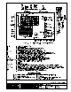


DJM3.2 MANUAL
TABLE OF CONTENTS
Page
I. APPLICATION............................................................................................................ 1
II. SERVICE.....................................................................................................................1
III. GENERAL DESCRIPTION ......................................................................................... 1
Basic Features..................................................................................................................................2
IV. WIRING....................................................................................................................... 3
V. OVERVIEW OF DJM OPERATION ............................................................................ 3
Supply Fan Operation......................................................................................................................3
Damper Operation ............................................................................................................................3
VI. SYSTEM TIMINGS...................................................................................................... 5
VII. DIPSWITCHES ........................................................................................................... 5
Switches............................................................................................................................................5
VIII. POTS .......................................................................................................................... 5
Main Board Pots Located on the Right Side of the DJM3.2 and 3.3 ...........................................6
IX. STATUS LIGHTS........................................................................................................ 6
LED 1 .................................................................................................................................................6
LED 2 .................................................................................................................................................6
LED 3 .................................................................................................................................................7
LED 4 .................................................................................................................................................7
X. AUTO BYPASS LOW LIMIT....................................................................................... 7
Resetting Low Limit .........................................................................................................................8
XI. DAY AND NIGHT OPERATING STRATEGIES.......................................................... 8
Blower/Damper Operation...............................................................................................................8
Day and Night Operating Strategies...............................................................................................8
XXX = Switch (SW.) can be "ON" or "OFF" ....................................................................................................... 8
Day Mode General Heat/Blower Operation....................................................................................8
Night Mode General Heat/Blower Operation .................................................................................9
XII. BASIC BURNER OPERATION................................................................................. 10
XIII. TEMPERATURE CONTROL – GENERAL OVERVIEW........................................... 10
XIV. MASTER SET-POINT............................................................................................... 10
The Optional Reset Inputs.............................................................................................................11
Night Heat........................................................................................................................................11
XV. INDUCED VOLTAGE ON REMOTE CONTROL WIRING........................................ 11
XVI. NIGHT HEAT THERMOSTATS ................................................................................ 11
Modulating Room Thermostat For Night Heat ............................................................................11
Make/Break Night Heat Thermostats............................................................................................12
XVII. ROOM RESET THERMOSTAT OPTIONS ............................................................... 12
Modulating Room Reset (continuous blower operation only).............................................. 12
ROOM RESET AUTHORITY TABLE ..............................................................................................13
Multiple Room Sensors .................................................................................................................15
BMS Reset (continuous blower only)................................................................................... 15
BMS RESET FROM VOLTAGE APPLIED TO + AND Β ................................................................16
Page i Revised: 03/11/99