
Installation Manual

Microinverter Safety
WARNING: Risk of skin burn. The body of the Enphase
Microinverter is the heat sink. Under normal operating
conditions, the temperature is 20°C above ambient, but
under extreme conditions the microinverter can reach a
temperature of 90°C. To reduce risk of burns, use cau-
tion when working with microinverters.
WARNING: Risk of electric shock. Risk of re. If the AC
cable on the microinverter is damaged, do not install the
microinverter.
WARNING: Risk of electric shock. Risk of re. Do not
attempt to repair the Enphase Microinverter; it contains
no user-serviceable parts. If it fails, contact Enphase cus-
tomer service to obtain an RMA (return merchandise au-
thorization) number and start the replacement process.
Tampering with or opening the Enphase Microinverter will
void the warranty.
+
WARNING: Risk of equipment damage. The S230 and
S280 may be paired only with 60-cell PV modules.
+
WARNING: Risk of re. The DC conductors of the PV
module must be labeled “PV Wire” or “PV Cable” when
paired with the S230 or S280 Microinverters.
+
WARNING: You must match the DC operating voltage
range of the PV module with the allowable input voltage
range of the Enphase Microinverter.
+
WARNING: The maximum open circuit voltage of the PV
module must not exceed the specied maximum input
DC voltage of the Enphase Microinverter.
+
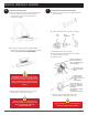
WARNING: Risk of equipment damage. The microinvert-
er must be installed under the module, out of rain and
sun. Do not mount the microinverter in a position that al-
lows long-term exposure to direct sunlight or in a vertical
orientation that allows water to collect in the DC connec-
tor recess. Do not install the microinverter vertically with
the DC connectors facing up.
WARNING: Risk of electric shock. Risk of re. Be aware
that only qualied personnel may connect the Enphase
Microinverter to the utility grid.
✓
NOTE: The Enphase Microinverter has eld-adjustable
voltage and frequency trip points that may need to be set,
depending upon local requirements. Only an authorized
installer with the permission and following requirements of
the local electrical authorities should make adjustments.
✓
NOTE: The Enphase Microinverter operates with sin-
gle-phase or three-phase electrical service.
Engage Cable and Accessory Safety
DANGER: Risk of electric shock. Do not install the En-
gage Cable terminator cap while power is connected.
WARNING: Risk of electric shock. Risk of re. When
stripping the sheath from the Engage Cable, make sure
the conductors are not damaged. If the exposed wires
are damaged, the system may not function properly.
WARNING: Risk of electric shock. Risk of re. Do not
leave AC connectors on the Engage Cable uncovered for
an extended period. If you do not replace the microin-
verter immediately, you must cover any unused connec-
tor with a sealing cap. Sealing caps may not be reused.
WARNING: Risk of electric shock. Risk of re. Make sure
protective sealing caps have been installed on all unused
AC connectors. Unused AC connectors are live when the
system is energized. Sealing caps may not be reused.
*
WARNING: Use the terminator only once. If you open
the terminator following installation, the latching mech-
anism is destroyed. Do not reuse the terminator. If the
latching mechanism is defective, do not use the ter-
minator. Do not circumvent or manipulate the latching
mechanism.
*
CAUTION: When installing the Engage Cable, secure
any loose cable to minimize tripping hazard
✓
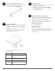
NOTE: Check the labeling on the Engage Cable drop
connectors to be sure that the cable matches the electri-
cal service at the site. Use 208 VAC (208 VAC three-
phase) Engage Cable at sites with three-phase 208 VAC
service, or use 240 VAC Engage Cable at sites with 240
VAC single-phase service.
✓
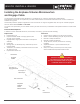
NOTE: There are two release-holes in the drop con-
nector on the cable. These are not for mounting but are
used to disconnect the connector. Keep these release
holes clear and accessible.
✓
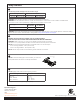
NOTE: When looping the Engage Cable, do not form
loops smaller than 4.75 inches (12 cm) in diameter.
✓
NOTE: If you need to remove a sealing cap, you must
use the Enphase disconnect tool or a #3 Phillips screw-
driver. Sealing caps may not be reused.
✓
NOTE: When installing the Engage Cable and accesso-
ries, adhere to the following:
• Do not expose the terminator cap or cable connections
to directed, pressurized liquid (water jets, etc.).
• Do not expose the terminator cap or cable connections
to continuous immersion.
• Do not expose the terminator cap or cable connections
to continuous tension (e.g., tension due to pulling or
bending the cable near the connection).
• Use only the connectors and cables provided.
• Do not allow contamination or debris in the connectors.
• Use the terminator cap and cable connections only
when all parts are present and intact.
• Do not install or use in potentially explosive environ-
ments.
• Do not allow the terminator to come into contact with
open ame.
• Make sure that all terminator cap seals are seated cor-
rectly in the wire organizer.
• Fit the terminator cap using only the prescribed tools
and in the prescribed manner.
• Use the terminator to seal the conductor end of the
Engage Cable; no other method is allowed.
✓
NOTE: Do not use the shipping cap to cover unused
connectors. The shipping cap does not provide an
adequate environmental seal. Enphase sealing caps are
required to protect against moisture ingress.
Safety Instructions, continued