
Installation Manual

3
1
Position the Enphase Engage™ Cable
a. Plan the cable length to allow drop connectors on
the Engage Cable align to with each PV module.
Allow extra length for slack, cable turns and any
obstructions.
b. Cut a length of Engage Cable to meet your
planned needs.
c. Lay out the cabling along the installed racking for
the AC branch circuit.
Install an AC Junction Box
a. Install an appropriately rated, off-the-shelf junction
box at a suitable location on the racking.
b. Provide an AC connection from the AC junction
box back to the electricity network connection us-
ing equipment and practices as required by local
jurisdictions.
See notes in Step Details.
2
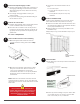
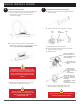
Attach the Microinverters to the PV Racking
a. Mark the approximate centers of each PV
module on the PV racking. See notes in Step
Details.
b. Mount the microinverter under the PV module,
away from rain and sun. Allow a minimum of
1.9 cm (0.75”) between the roof and the
microinverter. Also allow 1.3cm (0.50”) between
the back of the PV module and the top of the
microinverter.
Note: Install the microinverter as shown, with the
contoured side up. Failure to do so could allow the
microinverter to come in contact with the PV module
back sheet.
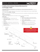
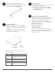
Dress the Cable
a. Use cable clips or tie wraps to attach the cable to
the racking.
b. Dress any excess cabling in loops so that it does
not contact the roof. Do not form loops smaller
than 4.75 inches (12 cm) in diameter.
Keep the drop
connector
release holes
clear and
accessible.
cable clip
release holes
5
4
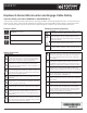
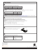
Create an Installation Map
Create a paper installation map to record microin-
verter serial numbers and position in the array.
a. Peel the removable serial number label from each
microinverter and afx it to the respective location
on the paper installation map.
b. Peel the label from the Envoy and afx it to the
installation map.
Always keep a copy of the installation map for your
records
afx
serial number
labels
Do not mount the microinverter in a
position that allows long-term exposure to
direct sunlight or in a vertical orientation
that allows water to collect in the cable
connector recess.
c. Torque the microinverter fasteners as fol-
lows.
Do not over torque:
• 5 N m (45-50 in-lbs) for 6 mm (1/4”)
hardware
• 9 N m (80-85 in-lbs) for 8 mm (5/16”)
hardware
This side up