
Installation Manual

9
8
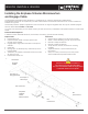
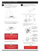
Connect the Cable to the AC Junction Box
Connect the Engage Cable into the AC branch circuit
junction box. See notes in Step Details.
10
Set Up and Activate System Monitoring
Referr to the Envoy-S Quick Install Guide or the
Envoy-S Installation and Operations Manual to install
the Envoy-S and set up system monitoring.
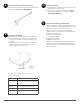
After you have installed the microinverters, the
high-level steps to complete the PV installation are:
a. Connect the Envoy-S.
b. Detect the microinverters.
c. Connect to Enlighten.
d. Register the system.
e. Build the virtual array.
Follow the procedures in the Envoy-S Quick Install
Guide or the Envoy-S Installation and Operations
Manual to activate system monitoring and complete
the PV installation.
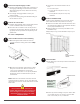
11
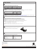
status LED
Connect the PV Modules
a. Mount the PV modules above the microinverters.
b. Connect the DC leads of each PV module to the
DC input connectors of the corresponding micro-
inverter.
c. Check the LED on the side of the microinverter.
The LED ashes six times at start up. All green
ashes indicate normal start up.
This table lists microinverter LED status for normal
operation after startup.
LED Indicates
Flashing green Normal operation. AC grid function is
normal and there is communication with
the Envoy-S.
Flashing
orange
The AC grid is normal but there is no
communication with the Envoy-S.
Flashing red The AC grid is not within specication.
Solid red There is an active DC ground resistance
fault.
Energize the System
a. If applicable, turn ON the AC disconnect or circuit
breaker for the branch circuit.
b. Turn ON the main utility-grid AC circuit breaker.
Your system will start producing power after a
ve-minute wait time.