
Installation Manual
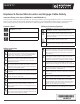

Step Details
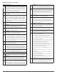
NOTE: Verify that AC voltage at the site is within range:
240 Volt AC Single-Phase 208 Volt AC Three-Phase
L1 to L2 211 to 264 VAC L1 to L2 to L3 183 to 229 VAC
L1, L2, to N 106 to 132 VAC L1, L2, L3 to N 106 to 132 VAC
WARNING: Only use electrical system components approved for wetlocations.
WARNING: Do not exceed the maximum number of microinverters in an AC branch circuit as listed in the table below.
Each branch circuit must be protected by a dedicated circuit breaker of 20 A or less.
Service type Max S230s
per branch
Max S280s
per branch
240 VAC single-phase 17 14
208 VAC balanced three-phase 24 21
WARNING: Size the AC wire gauge to account for voltage rise for both the branch circuit and all upstream conductors leading
back to the PCC. See the Technical Brief on Voltage Rise at http://www.enphase.com/support.
DANGER: ELECTRIC SHOCK HAZARD. THE DC CONDUCTORS OF
THIS PHOTOVOLTAIC SYSTEM ARE UNGROUNDED AND MAY BE ENERGIZED.
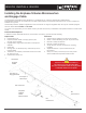
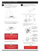
WARNING: Allow a minimum of 1.9 cm (0.75”) between the roof and the microinverter.
Also allow 1.3cm (0.50”) between the back of the PV module and the top of themicroinverter.
NOTE: Torque the microinverter fasteners to the values shown. Do not over torque:
• 1/4” mounting hardware – 5 N m (45-50 in-lbs)
• 5/16” mounting hardware – 9 N m (80-85 in-lbs)
NOTE: The AC output neutral is not bonded to ground inside the microinverter.
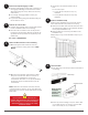
NOTE: To remove a sealing cap or AC connector, you must use
the Enphase disconnect tool or a #3 Phillips screwdriver.
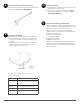
NOTE: Engage Cable uses the following wiring scheme.
240 Volt AC Single-Phase Wires 208 Volt AC Three-Phase Wires
Black – L1
Red – L2
White – Neutral
Green – Ground
Black – L1
Red – L2
Blue – L3
White – Neutral
Green – Ground
The green wire acts as equipment ground (EGC).
disconnect
tool
Enphase Energy, Inc.
1420 N. McDowell Blvd.
Petaluma, CA 94954
USA
info@enphaseenergy.com
http://www.enphase.com
© 2015 Enphase Energy Inc. All rights reserved.
2
3
6
8