
User Manual


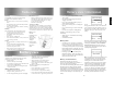


PREPARING YOUR RADIO FOR USE
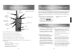
Attaching / removing the aerial
Attaching / removing the battery pack
1. To attach, carefully align the aerial with
the socket. Screw in the aerial clockwise
(taking care not to cross the thread) until it
is seated rmly with the accessory cover’s
rubber ring between the aerial and the top
of the radio. (A)
2. To remove, unscrew the aerial
anti-clockwise. (B)
1. To attach, locate the pegs on the bottom of the
battery into the slots on the radio and press
the top of the battery against the radio. Secure
battery by tightening the screw clockwise
by hand. (Do not use any implement or
overtighten). (C)
2. To remove, unscrew the locking screw
anti-clockwise and pull the battery away
from the top of the radio. (D)
A
B
C
D
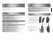
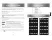
SWITCHING ON, RECEPTION
AND SWITCHING OFF
1. To switch on, press and hold the on/off button
(1) on the front of the radio.
2. When the radio has passed its diagnostic tests,
it will emit a fanfare tone.
3. The radio will enter standby mode. This is
indicated by the LED Amber ashing once
every 5 seconds, signalling that the radio is
ready for use.
4. Adjust the volume control to select the desired
volume level.
5. Using the channel buttons, ensure you have
the correct channel selected.
6. When receiving a valid signal, the LED will
illuminate steady green and audio will be
emitted from the radio’s speaker or audio
accessory (if attached)
7. When nished using the radio, switch off
by pressing and holding the on/off button
(1) until the radio beeps and the LED/LCD is
extinguished.
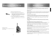
TRANSMITTING
1. Perform steps 1 through to 5 of Switching On,
Reception and Switching Off.
2. Before transmitting, monitor the channel and
make sure it is clear.
3. When receiving a signal, wait until the signal
stops before transmitting. The transceiver
cannot transmit and receive simultaneously.
4. Press the PTT (Push To Talk) button (4) to begin
your transmission. To conrm transmission the
LED illuminates red.
5. For best transmitted speech quality you must
talk directly into the radio’s microphone (9) at
around 4cm between your mouth and the radio
6. Please note: if you talk into the top of the
radio or with your mouth further away, you will
transmit poor quality speech.
7. When the transmission is nished release the
PTT button.
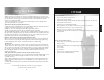
EU DECLARATION OF CONFORMITY
We. Entel UK Limited of:
320 Centennial Ave, Centennial Park,
Elstree. WD6 3TJ United Kingdom
Tel +44 208 236 0032
info@entel.co.uk
Declare under our sole responsibility that the
product ranges specied below conform to
the following standards or other nominative
documents;
HT446, HT500 series, HT700 V2 series,
HT800 V2 series, HT900 V2 series –
Land models only
EN 300 086-2V1.3.1; EN 301 489-1:2008-7;
EN 301 489-5 V1:3.1:2002-08:
EN 60950-1:2006 in accordance with
Directive 1999/5/EC
HT800 V2 series, HT900 V2 series –
Marine models
EN 301 178-2 V1.2:2007: EN 60945:2002:
EN 60950-1:2006 in accordance with
Directive 1999/5/EC
This declaration is valid for Directive 94/9/EC
until 19 April 2016
This declaration is valid for Directive 2014/34/
EU from 20 April 2016
HT800 V2 Series, HT900 V2 Series, HT500 Series
EN 60079-0:2012,
EN 60079-11:2012
Related certicates:
HT800 V2 Series, HT900 V2 Series
Sira 10ATEX2066X
HT9XX marking Ex ll 2 G Ex ib llC T4 Gb
HT8XX marking Ex ll 2 G Ex ib llA T4 Gb
HT500 Series
IECEx SIR 10.0097X
HT5XX marking Ex II 2 G Ex ib IIA T4 Gb
Sira Certication. Unit 6, Hawarden Industrial
Park, Hawarden, Deeside. CH5 3US, UK
Notied Body No. 0518
Quality Assurance Notication:
Intertek. Intertek House, Leatherhead
KT22 7SB, UK
Notied Body No. 0359
Name: Mike Jamieson
Position: Quality Manager
Date: 13 January 2016
Signed:
www.entel.co.uk
HT Series
HT500 | HT700 | HT800 | HT900 | HT446
Quick Start User Guide
Designed in the United Kingdom