Enterasys Matrix™ X Router DC Power Supply Installation Guide P/N 9034200
Electrical Hazard: Only qualified personnel should perform installation procedures. Riesgo Electrico: Solamente personal calificado debe realizar procedimientos de instalacion. Elektrischer Gefahrenhinweis: Installationen sollten nur durch ausgebildetes und qualifiziertes Personal vorgenommen werden. Notice Enterasys Networks reserves the right to make changes in specifications and other information contained in this document and its web site without prior notice.
Regulatory Compliance Information Federal Communications Commission (FCC) Notice This device complies with Part 15 of the FCC rules. Operation is subject to the following two conditions: (1) this device may not cause harmful interference, and (2) this device must accept any interference received, including interference that may cause undesired operation. NOTE: This equipment has been tested and found to comply with the limits for a class A digital device, pursuant to Part 15 of the FCC rules.
Electromagnetic Compatibility (EMC) This product complies with the following: 47 CFR Parts 2 and 15, CSA C108.8, 2006/95/EC, EN 55022, EN 61000‐3‐2, EN 61000‐3‐3, EN 55024, AS/NZS CISPR 22, VCCI V‐3. Compatibilidad Electromágnetica (EMC) Este producto de Enterasys cumple con lo siguiente: 47 CFR Partes 2 y 15, CSA C108.8, 89/336/EEC, EN 55022, EN 55024, EN 61000‐3‐2, EN 61000‐3‐3, AS/NZS CISPR 22, VCCI V‐3.
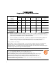
ѻક䇈ᯢк䰘ӊ Supplement to Product Instructions 䚼ӊৡ⿄ (Parts) 䞥ሲ䚼ӊ (Metal Parts) ⬉䏃ഫ (Circuit Modules) ⬉㓚ঞ⬉㓚㒘ӊ (Cables & Cable Assemblies) ล᭭㘮ড়⠽䚼ӊ (Plastic and Polymeric parts) ⬉䏃ᓔ݇ (Circuit Breakers) ƻ˖ 䪙 3E ᳝↦᳝ᆇ⠽䋼ܗ㋴ (Hazardous Substance) ∲ 䬝 ݁Ӌ䫀 ⒈㘨㣃 +J &G &U 3%% ⒈Ѡ㣃䝮 3%'( h ƻ ƻ h ƻ ƻ h ƻ ƻ h ƻ ƻ h ƻ ƻ h ƻ ƻ ƻ ƻ ƻ ƻ ƻ h ƻ ƻ h h ƻ ƻ 㸼⼎䆹᳝↦᳝ᆇ⠽䋼䆹䚼ӊ᠔᳝ഛ䋼ᴤ᭭Ёⱘ䞣ഛ SJ/T 11363-2006 ᷛޚ㾘ᅮⱘ䰤䞣㽕∖ҹϟDŽ Indicates that the concentration of the hazardou
VCCI Notice This is a class A product based on the standard of the Voluntary Control Council for Interference by Information Technology Equipment (VCCI). If this equipment is used in a domestic environment, radio disturbance may arise. When such trouble occurs, the user may be required to take corrective actions. BSMI EMC Statement — Taiwan This is a class A product. In a domestic environment this product may cause radio interference in which case the user may be required to take adequate measures.
Declaration of Conformity Application of Council Directive(s): Manufacturer’s Name: Manufacturer’s Address: European Representative Address: Conformance to Directive(s)/Product Standards: Equipment Type/Environment: 2004/108/EC 2006/95/EC Enterasys Networks, Inc. 50 Minuteman Road Andover, MA 01810 USA Enterasys Networks, Ltd.
Enterasys Networks, Inc. Firmware License Agreement BEFORE OPENING OR UTILIZING THE ENCLOSED PRODUCT, CAREFULLY READ THIS LICENSE AGREEMENT. This document is an agreement (“Agreement”) between the end user (“You”) and Enterasys Networks, Inc.
4. EXPORT RESTRICTIONS. You understand that Enterasys and its Affiliates are subject to regulation by agencies of the U.S. Government, including the U.S. Department of Commerce, which prohibit export or diversion of certain technical products to certain countries, unless a license to export the product is obtained from the U.S. Government or an exception from obtaining such license may be relied upon by the exporting party.
8. AUDIT RIGHTS. You hereby acknowledge that the intellectual property rights associated with the Program are of critical value to Enterasys, and, accordingly, You hereby agree to maintain complete books, records and accounts showing (i) license fees due and paid, and (ii) the use, copying and deployment of the Program.
x
Contents Chapter 1: DC Power Supply Installation Overview of the DC Power Supply .....................................................................................................1-2 Power Supply Redundancy Planning ..........................................................................................1-4 Installation Site Requirements ...........................................................................................................1-4 Pre-Installation Tasks ..................................
xii
About This Guide This guide describes the Enterasys Matrix™ X Router DC power supply features and specifications, and provides information to install the power supply in an Enterasys Matrix™ X chassis. Who Should Use This Guide This guide is intended for a network administrator who is responsible for installing and setting up the Enterasys Matrix™ X Router system. Electrical Hazard: Only qualified personnel should install or service this unit.
Conventions Used in This Guide Documentation can be accessed on the World Wide Web, at the following URL: http://www.enterasys.com/support/manuals/ Conventions Used in This Guide The following conventions are used in this guide: Note: Calls the reader’s attention to any item of information that may be of special importance. Caution: Contains information essential to avoid damage to the equipment. Precaución: Contiene información esencial para prevenir dañar el equipo.
Getting Help Getting Help For additional support related to the DC power supply or this document, contact Enterasys Networks using one of the following methods: World Wide Web http://www.enterasys.com/support 1-800-872-8440 (toll-free in U.S. and Canada) For the Enterasys Networks Support toll-free number in your country: Phone http://www.enterasys.com/support support@enterasys.com Internet mail To expedite your message, please type [X-Router] in the subject line.
Getting Help xvi About This Guide
1 DC Power Supply Installation Electrical Hazard: Only qualified personnel should perform installation procedures. Riesgo Electrico: Solamente personal calificado debe realizar procedimientos de instalacion. Elektrischer Gefahrenhinweis: Installationen sollten nur durch ausgebildetes und qualifiziertes Personal vorgenommen werden. This chapter provides installation instructions for the Enterasys Matrix™ X Router DC power supply module (X‐DC).
Overview of the DC Power Supply Overview of the DC Power Supply The DC power supply (X‐DC) can be used in the Enterasys Matrix™ X16‐C, X8‐C, and X4‐C chassis in place of the standard AC power supplies (X‐AC). The DC power supply connects a ‐48/‐60 VDC battery voltage to the backplane of the Enterasys Matrix™ X chassis. Each power supply provides a maximum of 1500 Watts of power. The DC power supply also provides a +5 VDC auxiliary output.
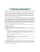
Overview of the DC Power Supply Figure 1-2 Back View of the DC Power Supply 1 1 Connector The DC power supply provides the following features: • Input Overload Protection As shown in Figure 1‐1 on page 1‐2, the power supply has a 50A circuit breaker on the front panel, to protect against internal damage due to a catastrophic failure. • Redundancy A maximum of six supplies can be operated in parallel, sharing a common power bus.
Installation Site Requirements Power Supply Redundancy Planning Because chassis system components consume varying amounts of electrical power, Enterasys recommend consulting the module power specifications in “Power Supply Redundancy” on page 2‐2 to guide you in installing the proper number of power supplies for your configuration. Installation Site Requirements The DC power supply must be installed in an Enterasys Matrix™ X chassis located in a Restricted Access Location (RAL).
Pre-Installation Tasks Pre-Installation Tasks Complete the following tasks before installing the DC power supply: • Verify DC Power Compliance of Matrix X Modules • Prepare Site Wiring for DC Power Installation (page 1‐8) Verify DC Power Compliance of Matrix X Modules All installed modules must meet both the 940 part number and the 940 revision minimum requirements for DC power.
Pre-Installation Tasks Note: In the CLI output for show system hardware, model name part numbers of modules are labeled “Part number.” 2. Table 1-1 Use the information from the output of the show system hardware command to fill out the worksheet in Table 1‐1 for each module as follows: a. Use the value of “940 Part number:” from the output of the show system hardware command to fill out the 940 Part Number section of Table 1‐1. b.
Pre-Installation Tasks New DC Power Matrix X System Installations If the system is a new Matrix X DC‐powered installation, follow this procedure to verify DC power compliance of all modules: 1. Obtain the model name and serial number from the front panel of each module to be installed. 2. Using the model name and serial number, fill out the worksheet in Table 1‐2. Table 1-2 Worksheet: DC Compliance of Modules for New DC Systems Model Part No. Example: X-CM-00 3.
Pre-Installation Tasks Table 1-3 Minimum Revision of X Modules for DC Power Model Name Minimum 940 Part Number Minimum 940 Revision X-CM-00 4179 5A1 X-T32-00 4167 5A2 X-G32-00 4161 5A3 X-M2-00 4054 5H X-M8-01 4162 5A X-GT16-00 3977 5A X16-FM 4059 5C X8-FM 4055 5B X4-FM 4050 5B X-FAN 4085 5B X-FAN-AC N/A N/A 1.
Unpacking the DC Power Supply Warning: To reduce the risk of electric shock or energy hazards: 1. Connect to a reliably grounded 48V source. 2. The branch circuit over current protection must be rated at a maximum 50A for the device. 3. Use only 10mm² or 6 AWG 75C solid copper wires on the device. 4. A readily accessible disconnect device that is suitably approved and rated shall be incorporated in the field wiring. 5.
Installing the DC Power Supply Table 1-4 Contents of X-DC Carton Item Quantity X-DC power supply 1 Plastic bag containing 5 nuts, 5 lock washers, and two 2-hole compression lugs. 1 Enterasys Matrix X Router DC Power Supply Notice 1 3. Remove the tape seal on the non‐conductive bag to remove the module. 4. Perform a visual inspection of the power supply and cable harness for any signs of physical damage. Contact Enterasys Networks if there are any signs of damage.
Installing the DC Power Supply 2. Remove the vent plate covering all power supply slots by loosening the top and bottom captive screws, as shown in Figure 1‐3. Note: The vent plate cannot be replaced over DC power supplies. Enterasys Networks recommends that you store the vent plate in a safe location in case of future reuse. Figure 1-3 Removing Power Supply Vent Plate 1 2 Power supply slot (PS1) Power supply coverplate 3 4 Vent plate Captive screws (2) 3.
Installing the DC Power Supply 5. Hold the power supply by placing one hand on the handle located on the front panel and using your other hand to support the power supply. 6. Position the power supply with the flange and captive screw pointing up (or to the right for the Enterasys Matrix™ X4‐C chassis) and align with the slot opening. Caution: Forcing a misaligned power supply into place can damage the power supply or chassis backplane.
Installing the DC Power Supply Figure 1-5 1 Removing Blank Coverplate from Power Supply Slot Power supply slot 2 2 Power supply coverplate 3 Captive screw 10. Connect the chassis to earth ground utilizing the earth ground connection on the back of the unit. a. Cut an 8 AWG (62 mm) stranded copper wire to a length suitable for connecting the grounding location of the chassis to the building earth ground. b. Install a listed 2‐hole, compression‐type connector on both ends of the grounding wire.
Removing a Power Supply b. Place the lock washers over the positive and negative studs. c. Place the nuts over the lock washers and tighten. Torque applied must be 36 in‐lb. 13. Replace the plastic shield. 14. Repeat steps 9 through 12 for each power supply. 15. Connect the DC input wiring to the DC power source. 16. Switch the branch circuit disconnect device to allow power to reach the DC power supply. 17. Set the circuit breakers on each DC power supply to On.
Removing a Power Supply Caution: If you want to operate the chassis with only one power supply, be sure to install the coverplate in place of the removed power supply to contain EMI radiation and ensure proper air circulation. Precaución: Si desea trabajar sólo con una fuente de poder, no olvide colocar la tapa en el compartimiento de la fuente de poder que haya eliminado, para reducir la interferencia electromagnética y para asegurar una buena ventilación.
Removing a Power Supply 1-16 DC Power Supply Installation
2 DC Power Supply Specifications This chapter provides the DC power supply specifications and regulatory compliance information. Specifications Table 2‐1 lists the physical specifications. Table 2‐2 lists the electrical specifications. Table 2-1 Physical Specifications Item Specification Dimensions 4.04 H x 13.87 W x 34.93 D (cm) 1.59 H x 5.46 W x 13.75 D (in.) Weight 2.38 kg (5.
Power Supply Redundancy Compression Lugs The DC power supply positive and negative bolt patterns match up to a 1/4‐inch diameter, 2‐hole compression lug spaced 5/8‐inch on center. This compression lug must terminate to a receptacle ready to crimp to 6 AWG. Enterasys Networks provides two lugs matching these requirements with the DC power supply.
Power Supply Redundancy Table 2-3 Module Power Specifications @ 48 VDC Module Power (Watts) Thermal Output (BTU/HR) CM 97 Watts 331.1 BTU/HR Fan tray 85 Watts 290.1 BTU/HR X4-FM 30 Watts 102.4 BTU/HR X8-FM 62 Watts 211.6 BTU/HR X16-FM 98 Watts 334.5 BTU/HR X-GT16-00 155 Watts1 520.0 BTU/HR X-T32-00 155 Watts 520.0 BTU/HR X-G32-00 155 Watts 520.0 BTU/HR X-M2-00 155 Watts 520.0 BTU/HR X-M8-01 190 Watts 648.0 BTU/HR 1. The actual power draw of the X-GT16-00 is 105 Watts.
Regulatory Compliance Regulatory Compliance The DC power supply meets the safety and electromagnetic compatibility (EMC) requirements listed in Table 2‐5: Table 2-5 2-4 Compliance Standards Regulatory Compliance Standards Safety UL 60950, CSA C22.2 No. 60950, 2006/95/EC, EN 60950, IEC 60950, EN 60825, 21 CFR 1040.10 Electromagnetic Compatibility (EMC) 47 CFR Parts 2 and 15, CSA C108.