X-Pedition™ Security Router XSR User’s Guide Version 7.
Electrical Hazard: Only qualified personnel should perform installation procedures. Riesgo Electrico: Solamente personal calificado debe realizar procedimientos de instalacion. Elektrischer Gefahrenhinweis: Installationen sollten nur durch ausgebildetes und qualifiziertes Personal vorgenommen werden. Notice Enterasys Networks reserves the right to make changes in specifications and other information contained in this document and its web site without prior notice.
Regulatory Compliance Information Federal Communications Commission (FCC) Notice The XSR complies with Title 47, Part 15, Class A of FCC rules. Operation is subject to the following two conditions: • This device may not cause harmful interference. • This device must accept any interference received, including interference that may cause undesired operation. NOTE: The XSR has been tested and found to comply with the limits for a class A digital device, pursuant to Part 15 of the FCC rules.
Industry Canada Notices This digital apparatus does not exceed the class A limits for radio noise emissions from digital apparatus set out in the Radio Interference Regulations of the Canadian Department of Communications. Le présent appareil numérique n’émet pas de bruits radioélectriques dépassant les limites applicables aux appareils numériques de la class A prescrites dans le Règlement sur le brouillage radioélectrique édicté par le ministère des Communications du Canada.
Electromagnetic Compatibility (EMC) This product complies with the following: 47 CFR Parts 2 and 15, CSA C108.8, 89/336/EEC, EN 55022, EN 55024, EN 61000‐3‐2, EN 61000‐3‐3, AS/NZS CISPR 22, and VCCI V‐3. Compatibilidad Electromágnetica (EMC) Este producto de Enterasys cumple con lo siguiente: 47 CFR Partes 2 y 15, CSA C108.8, 89/336/EEC, EN 55022, EN 55024, EN 61000‐3‐2, EN 61000‐3‐3, AS/NZS CISPR 22, VCCI V‐3.
Declaration of Conformity Application of Council Directive(s): Manufacturer’s Name: Manufacturer’s Address: European Representative Address: 89/336/EEC 73/23/EEC Enterasys Networks, Inc. 50 Minuteman Road Andover, MA 01810 USA Enterasys Networks, Ltd.
Independent Communications Authority of South Africa This product complies with the terms of the provisions of section 54(1) of the Telecommunications Act (Act 103 of 1996) and the Telecommunications Regulation prescribed under the Post Office Act (Act 44 of 1958). TE-2002/195 TE-2002/190 APPROVED APPROVED TE-2003/112 TE-2003/113 APPROVED APPROVED SS/366.
Enterasys Networks, Inc. Firmware License Agreement BEFORE OPENING OR UTILIZING THE ENCLOSED PRODUCT, CAREFULLY READ THIS LICENSE AGREEMENT. This document is an agreement (“Agreement”) between the end user (“You”) and Enterasys Networks, Inc.
4. EXPORT RESTRICTIONS. You understand that Enterasys and its Affiliates are subject to regulation by agencies of the U.S. Government, including the U.S. Department of Commerce, which prohibit export or diversion of certain technical products to certain countries, unless a license to export the Program is obtained from the U.S. Government or an exception from obtaining such license may be relied upon by the exporting party.
10. ENFORCEMENT. You acknowledge and agree that any breach of Sections 2, 4, or 9 of this Agreement by You may cause Enterasys irreparable damage for which recovery of money damages would be inadequate, and that Enterasys may be entitled to seek timely injunctive relief to protect Enterasys’ rights under this Agreement in addition to any and all remedies available at law. 11. ASSIGNMENT.
x
Contents Preface Contents of the Guide ................................................................................................................................... xxvii Conventions Used in This Guide ..................................................................................................................xxviii Getting Help ....................................................................................................................................................
Configuring an Interface ................................................................................................................... 2-22 Displaying Interface Attributes .......................................................................................................... 2-22 Managing Message Logs ....................................................................................................................... 2-23 Logging Commands ..........................................................
Chapter 3: Managing LAN/WAN Interfaces Overview of LAN Interfaces ............................................................................................................................ 3-1 LAN Features ................................................................................................................................................. 3-1 Configuring the LAN ......................................................................................................................................
Secondary IP ............................................................................................................................................ 5-7 Interface & Secondary IP.................................................................................................................... 5-7 ARP & Secondary IP .......................................................................................................................... 5-8 ICMP & Secondary IP............................................
Load Balancing ................................................................................................................................. 5-31 ARP Process on a VRRP Router ..................................................................................................... 5-31 Host ARP.......................................................................................................................................... 5-31 Proxy ARP ................................................................
Filter Lists ......................................................................................................................................... 6-12 Community Lists ............................................................................................................................... 6-12 Route Maps ...................................................................................................................................... 6-12 Regular Expressions ....................................
Describing the XSR’s PIM-SM v2 Features .................................................................................................... 7-7 Phase 1: Building a Shared Tree ............................................................................................................. 7-8 Phase 2: Building Shortest Path Tree Between Sender & RP ................................................................. 7-8 Phase 3: Building Shortest Path Tree Between Sender & Receiver ...............................
Chapter 9: Configuring Frame Relay Overview ......................................................................................................................................................... 9-1 Virtual Circuits .................................................................................................................................... 9-1 DLCIs..................................................................................................................................................
Configuring ISDN Callback .................................................................................................................. 10-12 Point-to-Point with Matched Calling/Called Numbers ..................................................................... 10-12 Point-to-Point with Different Calling/Called Numbers ..................................................................... 10-12 Point-to-Multipoint with One Neighbor .......................................................................
Backup Using ISDN ............................................................................................................................. 10-37 Node A (Backed-up Node) Configuration ....................................................................................... 10-37 Node C (Called Node) Configuration .............................................................................................. 10-38 Configuration for Backup with MLPPP Bundle ...................................................
Measuring Bandwidth Utilization ...................................................................................................... 12-5 Describing Priority Queues............................................................................................................... 12-5 Configuring Priority Queues ............................................................................................................. 12-5 Describing Traffic Policing ..........................................................
ADSL Hardware ..................................................................................................................................... 13-5 NIM Card .......................................................................................................................................... 13-5 ADSL on the Motherboard ................................................................................................................ 13-6 DSP Firmware ...................................................
Server 1 .......................................................................................................................................... 14-17 Server 2 .......................................................................................................................................... 14-18 Client .............................................................................................................................................. 14-18 Limitations ....................................
DHCP Client Services .................................................................................................................................. 15-6 Router Option ......................................................................................................................................... 15-6 Parameter Request List Option .............................................................................................................. 15-6 DHCP Client Interaction ............................
Application Level Commands ......................................................................................................... 16-13 Application Level Gateway ............................................................................................................. 16-13 On Board URL Filtering .................................................................................................................. 16-14 Denial of Service (DoS) Attack Protection .............................................
DOS Attacks Blocked Counters........................................................................................................B-12 DOS Attacks Blocked Table .............................................................................................................B-12 VPN MIB Tables ...........................................................................................................................................B-12 etsysVpnIkePeer Table ......................................................
Preface This guide provides a general overview of the XSR hardware and software features. It describes how to configure and maintain the router. Refer to the XSR CLI Reference Guide and the XSR Getting Started Guide for information not contained in this document. This guide is written for administrators who want to configure the XSR or experienced users who are knowledgeable of basic networking principles.
Conventions Used in This Guide • Chapter 11, Configuring ISDN, outlines how to set up the Integrated Services Digital Network protocol on the XSR for BRI, PRI and leased line applications. ISDN protocol tracing and partial decoding of Q921 and Q931 frames is also described.
Conventions Used in This Guide Warning: Warns against an action that could result in personal injury or death. Advertencia: Advierte contra una acción que pudiera resultar en lesión corporal o la muerte. Warnhinweis: Warnung vor Handlungen, die zu Verletzung von Personen oder gar Todesfällen führen können! Bold/En negrilla Text in boldface indicates values you type using the keyboard or select using the mouse (for example, a:\setup). Default settings may also appear in bold.
Getting Help Getting Help For additional support related to the XSR, contact Enterasys Networks by one of these methods: World Wide Web http://www.enterasys.com Phone (978) 684-1000 1-800-872-8440 (toll-free in U.S. and Canada) For the Enterasys Networks Support toll-free number in your country: http://www.enterasys.com/support/gtac-all.html Internet mail support@enterasys.com To expedite your message, please type [xsr] in the subject line. FTP Login Password ftp://ftp.enterasys.
1 Overview This chapter briefly describes the functionality of the XSR. Refer to the following chapters in this manual for details on how to configure this functionality and the XSR CLI Reference Guide for a description of associated CLI commands and examples.
and data-compression negotiation. Also supported: PPPoE client and sub-interface monitoring, and Multilink PPP protocols as well as Dial on Demand (DoD), Bandwidth on Demand (BoD), Multi-Class MLPPP. 1-2 Overview • IP Protocol - IP supports interconnected systems of packet-switched computer communication networks. It uses a 32-bit addressing scheme where an IP address is represented by four fields, each containing 8-bit numbers.
• Quality of Service - The XSR provides traffic classification using IP Precedence and DSCP bits, bandwidth control via metered, policed and prioritized traffic queues, and queue management utilizing Tail Drop, Random and Weighted Early Detection (RED, WRED). Also, QoS on Input including classification based on class maps (similar to QoS on Output), marking per traffic flow (DSCP and IP precedence fields), and policing per traffic class, and QoS over VPN.
1-4 Overview
2 Managing the XSR The XSR can be managed via three interfaces with varying levels of control: the Command Line Interface (CLI) for full configuration, performance and fault management; the Simple Network Management Protocol (SNMP) for remote monitoring and firmware upgrades, and the Web for gathering version information. Utilizing the Command Line Interface The Command Line Interface (CLI) is a widely used tool to access and control configurable parameters of the XSR.
Utilizing the Command Line Interface Using the Console Port to Remotely Control the XSR The XSR’s Console port can also be connected to a modem for the purpose of remote console control. Make the connection with a straight-through cable and enter the following XSR commands: XSR(config)#interface serial 0 XSR(config-if)#physical-layer async XSR(config-if)#clock rate 9600 XSR(config-if)#encapsulation ppp XSR(config-if)#ip address 192.168.10.1 255.255.255.
Utilizing the Command Line Interface Terminal Commands If you want to display identification information about the current terminal connection, issue the show whoami command. Refer to the XSR Getting Started Guide and XSR CLI Reference Guide for more information on commands. Connecting via Telnet Once the XSR is properly configured with a valid IP address, you can remotely connect to the CLI via Telnet using the default user admin with no password. Later, you can create users with the username command.
Utilizing the Command Line Interface PuTTY and other shareware programs are compatible with the XSR’s SSH server. Refer to the XSR Getting Started and CLI Reference guides for more details. Accessing the Initial Prompt The CLI is protected by security. Before you can access EXEC mode, you must enter a valid password. This mode lets you test basic connectivity of the XSR but does not permit you to change or monitor the router’s configuration.
Utilizing the Command Line Interface Managing the Session A first-time CLI session is set up with default attributes; e.g., the session is set to time out after 1800 seconds of idle time. You can reconfigure session values such as create users, passwords, and login banners, and set Telnet and Web access. Refer to the XSR CLI Reference Guide for details about these commands.
Utilizing the Command Line Interface • Backwardly compatible/transparent to those not requiring RAI. • Console display of RAI progress. • Console interrupt of RAI process at any time. • CLI configurable RAI loading. Persistent, 5-minute try, and none (disable). • No rebooting required to activate configuration. • Hostname choices are flexible to include/exclude domain and canned names as well for the configuration file.
Utilizing the Command Line Interface DHCP client over the LAN: • Operational over an Ethernet interface only on the lowest slot/card/port only. • Uses the options field for TFTP server, IP address, host name and config file. • Optionally uses Reverse DNS if options are not populated. At a branch site, the XSR supports the following features over a PPP IETF serial interface: • Operational on Serial NIM interfaces only - Lowest slot/card/port only. • Supports standard physical Serial media-types.
Utilizing the Command Line Interface RAI checks each DLCI, up to 30, on a given interface for a Bootp response, an rDNS server and a TFTP server with a configuration file. The first DLCI that accomplishes this will be chosen. If the connection fails, RAI will reset itself and restart at Phase 1, next media-type. If the DLCI does not have all of the correct servers and responses, the next DLCI on that interface is queried.
Utilizing the Command Line Interface With bootp enabled, DHCP relay and server functionality is disabled on this DLCI for broadcast packets entering from this DLCI. Unicast bootp requests are still forwarded to the server. Configuration on a DLCI by DLCI basis is supported for a bootp response, requiring that a statically-mapped DLCI number be configured with a corresponding IP address. This mapping is valid for both point-to-point and multi-point sub-interfaces.
Utilizing the Command Line Interface PPP RAI over a Leased Line PPP over a leased line performs similarly to Frame Relay RAI over a serial link via a leased Telco line. When PPP negotiation is successful, a point-to-point connection is established from the remote XSR to the central router. Then the remote XSR can obtain its IP address. But, you must assign a default peer IP address in the central router to give the remote XSR a valid IP address.
Utilizing the Command Line Interface The first phase establishes a physical connection (training) on the ADLS line. RAI ADSL attempts a physical connection on the first port of the ADSL card, waiting one minute for training to succeed. If it fails, RAI abandons ADSL RAI and moves to the next available RAI method. After training with the DSLAM, RAI must configure a proper PVC channel on the ADSL line.
Utilizing the Command Line Interface • Command Recall: Non-help commands are stored in the command history list buffer up to the last 32 commands. You can recall and edit previous commands using shortcut keys. For example: Ctrl+p/Ctrl+n will list the previous/next command respectively and can be applied repeatedly. The up-arrow or down-arrow keys provide the same feature if your terminal supports these keys. • Tab Completion: Pressing the TAB key or CTRL+I completes a command.
Utilizing the Command Line Interface Table 2-3 CLI Configuration Modes Mode Function Access Method Prompt User EXEC Password-protected mode: •Changes terminal settings •Performs basic tests •Displays system information Login process XSR> Privileged EXEC This mode: •Sets system operating values •Shows configuration parameters •Saves/copies configurations Enter enable in User EXEC XSR# Global Sets system-wide values.
Utilizing the Command Line Interface 4. Some attributes can be set at this level without acquiring other modes. For example: accesslist access-list-num [deny | permit] [parameter [parameter…]] 5. Show commands can all be entered at EXEC, Privileged EXEC or higher modes. User EXEC Mode You enter User EXEC (or simply EXEC) mode after logging in. The following commands can be entered in EXEC mode: disable, enable, exit, help, isdn, ping, show, telnet, terminal and traceroute.
Utilizing the Command Line Interface Mode Examples Consider the following examples to change configuration mode: XSR>enable + Acquires Privileged EXEC mode XSR#config terminal + Acquires Global configuration mode XSR(config)#interface fastethernet 1 + Acquires Interface mode XSR(config-if)#ip address 192.168.2.2.255.255.255.
Utilizing the Command Line Interface CLI Command Limits CLI commands on the XSR are bounded by the following: • Total number of characters in a command line/help message: 299 • Total number of words in a command line: 127 • Number of command history entries recalled: 31 • Total number of characters in a prompt: 1023 • Total number of characters in system name: 31 Describing Ports and Interfaces Technically, a port is a physical connector with some physical layer values.
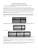
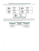
Utilizing the Command Line Interface Supported Ports The XSR supports the following port types: • Single-channel ports: Fast- and GigabitEthernet, Sync/Async serial, ATM • Multiple-channel type ports: BRI, T1/E1 Numbering XSR Slots, Cards, and Ports The syntax for XSR slot, card, and port numbering on the CLI, illustrated in Figure 2-2, is: slot#/card#/port# These parameters indicate: • slot #: (motherboard is zero), (XSR 1800: 1/2, 3020/3150: 1/2, 3250: 0-2) • card #: NIM card number (FastEth: 1/2, Giga
Utilizing the Command Line Interface • Virtual Interfaces: – Loopback - Range 0 to 15. Interface type: Internal Loopback. – Dialer - Range: 0 to 255, Interface type: Dialer. – VPN - Range: 0 to 255, Interface type: VPN tunnel/Dialer. – Multilink - Range: 1 to 32767, Interface type: VPN tunnel. – Frame Relay DLCI - Range: 16 to 1007, Interface type: Serial/FR.
Utilizing the Command Line Interface • BRI-Dialer (IDSN) Example interface dialer 0 + Configures dialer interface 0 ip address 2.2.2.2 255.255.255.0 + Sets IP address/subnet on port encapsulation + Interface/Sub-interface Behavior XSR interfaces and sub-interfaces, channels and channel-groups are added and deleted differently depending on the particular interface. Interface characteristics are as follows: • T1/E1 Controller - Creating a channel group adds a serial interface.
Utilizing the Command Line Interface – Switched: When configuring a switched BRI connection, three serial sub-interfaces are automatically created when you enter: interface bri 2/1 isdn switch-type basic-ni1 – The following sub-interfaces are added: interface serial 2/1:0 interface serial 2/1:1 interface serial 2/1:2 – These serial sub-interfaces are removed with the no isdn switch-type command: interface bri 2/1 no isdn switch-type + This deletes serial ports 2/1:0, 2/1:1 and 2/1:2 Entering Comma
Utilizing the Command Line Interface Deleting Table Entries There are two ways to delete an entry from a table depending on the table type. Type (e.g.): XSR(config)#no arp 1.1.1.1 e45e.ffe5.ffee + removes the arp entry related to row 1.1.1.1. where no is the command that negates the previous operation and arp is the associated table type. A second example is entered as follows: XSR(config)#no access-list 1 + removes access-list 1 where no is the command that clears the access-list.
Utilizing the Command Line Interface Ports can be enabled or disabled, configured for default settings, associated tables, clock rate, priority group, and encapsulation, for example. Refer to the XSR CLI Reference Guide for more details on Interface mode commands. Note: All interfaces are disabled by default. Enabling an Interface The following command enables an interface.
Utilizing the Command Line Interface Managing Message Logs Messages produced by the XSR, whether alarms or events, as well as link state changes for critical ports and a management authentication log, can be routed to various destinations with the logging command. And by issuing the no logging command, you can block messages to a site while permitting transmission to others.
Utilizing the Command Line Interface • Contents of stacks (task stacks, interrupt stack) • Status of one special task (packet processor by default) • Code around the crash program counter • Task message queues • Memory management statistics • Task stack traces for all tasks The router can store one Fault Report, retaining the first Fault Report in case of multiple failures.
Utilizing the Command Line Interface Using the Real-Time Clock The XSR’s Real-Time Clock (RTC) is employed by other system software modules to time-stamp events, alarms and is useful when no network clock source is accessible. It is normally synchronized with a master clock source over the network using the Simple Network Time Protocol (SNTP) but can also synchronize with the battery-supported RTC chip. For SNTP configuration, see Chapter 3: Software Configuration in the XSR Getting Started Guide.
Utilizing the Command Line Interface Resetting the Configuration to Factory Default In situations where the XSR has invalid software or a problem booting up, you can reset the router and return it to its factory default settings by accessing Bootrom Monitor Mode. Take these steps: 1. Power up with a serial Com connection. 2. During the first five seconds of system initialization, press CTRL-C to enter Bootrom mode. 3.
Utilizing the Command Line Interface Configuration Save Options There are several options available regarding configuration: • If you want to make your running configuration the new startup configuration, you can save it to Flash memory with the copy running-config startup-config command. • If you want to convert your startup configuration into the running configuration, you can issue the reload command which reboots the XSR and reloads the startup configuration.
Utilizing the Command Line Interface Note: If you have inadvertently added errors to the CLI script file, the restoration of startupconfig will be stopped at the error line. So, any commands after that line in startup-config are not executed. For more command details, refer to the XSR CLI Reference Guide. Uploading the Configuration/Crash Report An upload copies the XSR startup-configuration file (partial) to a system in a CLI script format using TFTP. You can later retrieve the file with TFTP.
Utilizing the Command Line Interface Managing the Software Image The XSR can store more than one software image in Flash. Creating Alternate Software Image Files The XSR can create multiple software images, a useful option if you want to quickly select an alternate image. For example, you can create two software image files: XSR1805_a.fls and xsr1805_b.fls. Begin the process by issuing the boot system command to create a boot-config file containing the name of your software file.
Utilizing the Command Line Interface • Optionally, if you have CompactFlash installed, you can download the firmware file to cflash: then perform Step 1 (see below) followed by the bu (lower-case u) command. • If you use the Cabletron TFTP/BOOTP Services application, which does not recognize long file names, first shorten the Bootrom file name to 8 characters or less with an extension, before beginning the download (i.e.: bootnew.fls). Rename the file after the download.
Utilizing the Command Line Interface 4. Using TFTP, transfer updateBootrom.fls from the network: XSR-1805#copy tftp://192.168.27.95/C:/tftpDir/ updateBootrom.fls flash:updateBootrom.fls Copy 'tftpDir/updateBootrom.fls' from server as 'updateBootrom.fls' into Flash(y/n) ? y !!!!!!!!!!!!!!!!!!!!!!!!!! Download from server done File size: 667172 bytes 5.
Utilizing the Command Line Interface Local Bootrom Upgrade Due to the change in the format of the Bootrom file between version 1.x and version 2.01, a transitional step is required when updating across these versions only. This transitional step can be avoided by using the Bootrom Update utility described above. When you are running a 1.x version of the Bootrom and you try to upgrade to version 2.01 of the Bootrom file, it will be rejected due to the change in format. bootrom_uncmp.
Utilizing the Command Line Interface – DOS-style full path (without the file name) of the site of the Bootrom file on the host PC. – The username and password to use when connecting to your FTP server on the host PC. 6. Verify the network boot values using the sn command. For example: XSR: sn Local IP address : 192.168.1.1 Remote IP address : 192.168.1.
Utilizing the Command Line Interface Programming 131072(0x20000) bytes at address 0xfffa0000 Programming 48299(0xbcab) bytes at address 0xfffc0000 Verifying Bootrom flash sectors Locking 3 Bootrom flash sectors Locking 8 Bootrom flash sectors ***** Bootrom update completed. ***** Do you want to remove the bootrom file bootrom_uncmp.fls? (y/n) y Using default Bootrom password. Use “bp” to change password 9. The system is not secure!!! Reboot the XSR by entering bw. 10.
Utilizing the Command Line Interface • If the power to XSR fails, try another reload • If a syntax error is indicated, examine your configuration for errors • If XSR crashes, do not retry reloading. Contact Technical Support EOS fallback is configurable from the CLI or via SNMP. Refer to the following section to configure the feature on the CLI or “Configuring EOS Fallback via SNMP” on page 2-35 for SNMP configuration instructions. Configuring EOS Fallback on the CLI 1. Upgrade the bootrom.
Utilizing the Command Line Interface 5. Set the operation to imageSetSelected: set 1.1.1.1 .1.3.6.1.4.1.5624.1.2.16.2.7.1.3.1 0100 6. Set the row to active: set 1.1.1.1 .1.3.6.1.4.1.5624.1.2.16.2.7.1.11.1 1 Note: The primary image cflash:xsr3004.fls must already exist in the XSR, otherwise the configuration will fail at this point. 7. Reboot the XSR to load the new image by configuring the following: • Create a row: set 1.1.1.1 .1.3.6.1.4.1.5624.1.2.16.2.7.1.11.
Memory Management When the XSR boots up, the checksum of these files is calculated and stored in volatile memory. From then on any time the content of those files is changed the hash is recalculated and stored. You can access the hash value in the etsysConfigMgmtPersistentStorageChSum SNMP object and compare it with previous queries to detect configuration changes to the managed entity.
Network Management through SNMP When the memory governor is asked to allow or deny a new resource, the decision is based on: • memory low watermark • extreme limit You can push the extreme limit of individual resources as long as the memory low watermark is not met. Once the low watermark is met and you wish to create more resources, you must then free up earlier configured resources.
Network Management through SNMP SNMP Informs SNMP Informs were first introduced in SNMPv2. An Inform is essentially nothing more than an acknowledged trap. That is, when a remote application receives an Inform it sends back an “I got it” message. When you send an Inform you use the remote engineID with the message and the securityName and engineID exist as a pair in the Remote User table.
Network Management through SNMP Alarm Management (Traps) The following events are supported by SNMP traps: snmpTrapColdStart, snmpTrapWarmStart, snmpTrapLinkDown, snmpTrapLinkUp, snmpTrapAuthFailure, entityTrapConfigChange, frameRelayTrapfrDLCIStatusChange, ospfTrapIfStateChange, ospfTrapVirtIfStateChange, ospfTrapNbrStateChange, ospfTrapVirtNbrStateChange, ospfTrapIfConfigError, ospfTrapVirtIfConfigError, ospfTrapIfAuthFailure, ospfTrapVirtIfAuthFailure, ospfTrapIfRxBadPacket, ospfTrapVirtIfRxBadPacket, o
Network Management through SNMP Latency (network delay) is measured with the formula: D(i)=(Ri-Si), which is the round-trip interval between sending and receiving the ICMP packet triggered by the initiator and echoed back by the target. Jitter (network delay variation) is the value between packets i and j as figured by the formula: D(i,j)=(Rj-Ri)-(Sj-Si). Since the XSR measures the round trip, Ri indicates the receive interval at the source instead of the target.
Network Management through SNMP Via SNMP The following example creates a row in the aggregate measure table with owner userA. If the entry is created with owner monitor, replace 5.117.115.101.114.65 with 7.109.111.110.105.116.111.114. 1. Create a row (etsysSrvcLvlAggrMeasureStatus): 1.3.6.1.4.1.5624.1.2.39.1.4.2.1.18.5.117.115.101.114.65.1 = 5 (createAndWait) 2. Configure the destination address (etsysSrvcLvlNetMeasureDst) in the network measure table: 1.3.6.1.4.1.5624.1.2.39.1.4.1.1.14.5.117.115.101.
Network Management through SNMP Query a Measurement Now that you have performed the previous actions, you can query the measurement result. Via CLI The following command displays rtr output: XSR#show rtr history Via SNMP 1. Query the etsysSrvcLvlHistoryTable (1.3.6.1.4.1.5624.1.2.39.1.3.1). Using the SLA Agent in SNMP The XSR’s SLA agent implements the Enterasys Service Level Reporting MIB and supported metrics as detailed in the following tables, which may cross-reference each other.
Network Management through SNMP Software Image Download using NetSight The NetSight Remote Administrator application can download an image to the XSR using TFTP. The software image download is initiated through NetSight using an SNMP set command, which triggers a TFTP download session initiated from the XSR. Note: The XSR does not support an off-line download triggered by SNMP. That is, when you use NetSight to download an image, a dialog box will pop up with a check box titled Online download.
Accessing the XSR Through the Web 1. Write a plain ASCII file containing the CLI commands you want entered. For example: interface FastEthernet2 ip address 192.168.19.1 255.255.255.0 no shutdown 2. Save and move the file to the root directory of the TFTP server on your PC. 3. Use SNMPv3 to create a row in the Configuration Management MIB. For example, CreateAndWait: 1.3.6.1.4.1.5624.1.2.16.2.7.1.11.1 = 5 If you read the table, one row should be added. 4.
Network Management Tools Using the CLI for Downloads TFTP can be used to transfer system firmware to the XSR remotely. A TFTP server must be running on the remote machine and the firmware image file must reside in the TFTP root directory of the server when using the copy tftp filename command. Using SNMP for Downloads You can use an SNMP manager to download or upload firmware from a remote server, and copy a configuration image file to the XSR. Only run-time/online mode downloads are supported.
3 Managing LAN/WAN Interfaces Overview of LAN Interfaces The XSR supports two 10/100 Base-T FastEthernet ports on the XSR 1800 Series branch routers and three 10/100/1000 Base-T GigabitEthernet ports on the XSR 3000 Series regional routers. All ports are capable of running in half- and full-duplex modes, and are ANSI/IEEE 802.3 and ANSI/ IEEE 802.3u compliant. These ports connect to an Ethernet network for LAN connectivity.
Configuring the LAN • Maximum Transmission Unit (MTU) - all frames less than or equal to 1518 bytes are accepted. MTU size is set using the ip mtu command.
Overview of WAN Interfaces Table 3-1 MIB-II Interface Statistics (continued) Variable Description ifInNUcastPkts Sum of non-unicast packets delivered to a higher layer protocol. IfInDiscards Sum of inbound packets discarded. IfInErrors Sum of inbound packets that contained errors. IfOutOctets Sum of octets transmitted on the interface ifOutUcastPkts Sum of subnetwork-unicast packets sent to the network. ifOutNUcastPkts Sum of non-unicast packets transmitted to the network.
Configuring the WAN • Clocking speed - For Sync interfaces, an external clock must be provided. Acceptable clock values range from 2400 Hz to 10 MHz. For Async interfaces, the clock is internally generated and can be set to the following values using clock rate: – 2400 Kbps – 4800 Kbps – 7200 Kbps – 9600 Kbps (default) – 14400 Kbps – 19200 Kbps – 28800 Kbps – 38400 Kbps – 57600 Kbps – 115200 Kbps • Statistics - all MIB-II interface statistics are supported.
Configuring the WAN The following example configures the asynchronous serial interface on NIM 2, port 0 with the following non-default values: PPP encapsulation, RS422 cabling, 57600 bps clock rate, MTU size of 1200 bytes, no parity, 7 databits and 2 stopbits. It also assigns the local IP address 192.168.1.1 to the interface.
Configuring the WAN 3-6 Managing LAN/WAN Interfaces
4 Configuring T1/E1 & T3/E3 Interfaces Overview The XSR provides Frame Relay and PPP service via T1/E1 and T3/E3 functionality as well as Drop and Insert features. T1/E1 Functionality The XSR provides a T1/E1 subsystem on a single NIM-based I/O card with a maximum of two installed NIMs. Depending on the card type and series, each card can support 1, 2 or 4 T1 or E1 physical ports. You can select either T1, at 1.544 Mbps interface rate per port, or E1, at 2.048 Mbps interface rate per port.
Features • Support for local and remote loopback • Support for an IP interface as a loopback (refer to the CLI Reference Guide for an example) • Timing - line and internal • Framing - T1: SF, ESF; E1: CRC4, NO-CRC4 • Line encoding - T1: AMI, B8ZS; E1: AMI, HDB3 • Data inversion • Loopback Tests - local, network line, network payload, inband FDL • Alarm detection - all levels of alarm/event detection and signaling • T1 Drop and Insert (D&I NIM) with One to One voice DS0 bypassing The follo
Features • Line rate - 34.368 Mbps • Full rate - 34.0995 Mbps (G751) • Sub-rate - approximately 3 Mbps increments up to 33 Mbps • Compatible DSUs supported – Cisco or Quick Eagle (formerly Digital Link) DL3100 E3 -300-33.
Features • Clear Channel service is similar to the full rate service except that the data stream rate is slightly higher because the framing overhead bits are also used to deliver data. – T3 - Not Available – E3 - 34.368Mbps payload T1 Drop & Insert One-to-One DS0 Bypassing The XSR’s 2-port D&I NIM is designed to cross-connect unused timeslots between the two ports and provide one T1/E1 line for both data and voice traffic, as shown in Figure 4-1.
Configuring Channelized T1/E1 Interfaces • The D&I NIM supports different framing and line coding on the CO T1 and PBX T1 ports (ESF versus D4, B8ZS versus AMI), but if the ports are not identically configured, the bypass relays will not restore the voice link in the case of an XSR failure or power outage. • The CO T1/E1 port supports one PPP or Frame Relay channel. • The T1E1 Drop & Insert NIM includes the same data functionality as the standard two-port Fractional T1E1 NIM.
Configuring Un-channelized T3/E3 Interfaces 9. Add any additional configuration commands required to enable IP- or PPP-related protocols. 10. Use the no shutdown and exit commands to enable the interface and return to configuration mode. Repeat the previous steps to configure more channel groups. XSR(config-if)#no shutdown Configuring Un-channelized T3/E3 Interfaces Perform the following steps to set up an un-channelized T3 or E3 port.
Troubleshooting T1/E1 & T3/E3 Links Troubleshooting T1/E1 & T3/E3 Links This section describes general procedures for troubleshooting T1/E1 lines on the XSR. The following flow diagram shows basic steps to perform.
Troubleshooting T1/E1 & T3/E3 Links Figure 4-3 T1/E1 & T3/E3 Physical Layer (Layer 1) Troubleshooting Flowchart Loss of Signal Loss of Signal/Loss of Frame Use the following commands to bring up the controller: controller t1 x framing Loss of Frame No Is the framing format correct? Yes Are the cables and connectors ok? No Connect or replace the cable Yes Use the following commands to change the LBO: cablelength long/short (T1) cablelength (T3) If your T1/E1 or T3/E3 controller still does not
Troubleshooting T1/E1 & T3/E3 Links 2. Restart the controller: XSR(config-controller)#no shutdown If the T1/E1or T3/E3 controller and line are not up, check that either the T3/E3 NIM LOS or LOF LEDs are shining or one of the following messages displays in the show controller output: • Receiver has loss of frame (LOF), or • Receiver has loss of signal (LOS) Complete the following steps if the receiver has loss of frame: 1.
Troubleshooting T1/E1 & T3/E3 Links Receive Remote Alarm Indication (RAI - Yellow Alarm) 1. Insert an external loopback cable into the T1/E1 or T3/E3 port. 2. Use the show controller command to check for alarms. To identify the type of the alarm, analyze the log report of the XSR. If alarms are reported, contact your service provider. 3. Remove the external loopback cable and the reconnect line. 4. Check the cabling. 5. Power cycle the XSR. 6.
Troubleshooting T1/E1 & T3/E3 Links Figure 4-5 T1/E1 & T3/E3 Alarm Analysis Troubleshooting Actions Flow (Part 2) Receive Remote Alarm Indication (Yellow alarm) - see Figure 1-2 Transmit Alarm Indication Signal (Blue alarm) - see Figure 1-2 Insert external loopback cable in the port No Does framing on the port match the line setting? No Are there any alarms? Yes Check the cabling Power cycle the XSR Check the cabling Yes Check the settings on the remote end Contact your service/ network provider C
Troubleshooting T1/E1 & T3/E3 Links Figure 4-6 T1/E1 & T3/E3 Error Events Analysis Troubleshooting Flowchart Error Events Analysis Is the slip seconds counter increasing? Yes Is the clock source derived from the network/line? No No Is the framing loss seconds counter increasing? Yes Is the framing type correct? No Use the following commands to set source clocking: controller t1 x clock source line Use the command below to verify the error counter is still: increasing: controller x Use these c
Troubleshooting T1/E1 & T3/E3 Links Framing Loss Seconds Increasing If framing loss seconds are present on the T1/E1 line, usually there is a framing problem. Perform the following steps to correct this problem: 1. Ensure the framing format configured on the controller port matches the framing format of the line. 2. Set the T1/E1 framing mode from Controller mode if needed. 3. (T1 Only) Change the line build out (LBO) using the cablelength long or cablelength short command if needed.
Troubleshooting T1/E1 & T3/E3 Links 4-14 Configuring T1/E1 & T3/E3 Interfaces
5 Configuring IP Overview This document describes the XSR’s IP protocol suite functionality including: • General IP features (ARP, ICMP, TCP, UDP, TFTP, Telnet, SSH, NAT, VRRP, Proxy DNS, et al.) • IP routing (RIP, OSPF, static routing, triggered-on-demand RIP updates) • VLAN routing • Applicable MIBs • Configuration examples IP protocol, the main protocol of the TCP/IP suite, interconnects systems of packet-switched computer communication networks.
General IP Features • The Router ID can be configured with the ip router-id command or, if not configured, automatically generated from the existing configuration. Alternately, the Router ID is automatically generated as the highest non-zero IP address among all loopback interfaces or, if no loopback interface is configured, the highest non-zero IP address among standard configured interfaces. A loopback interface can be configured with the interface loopback command.
General IP Features • • • Troubleshooting Tools – Ping – Traceroute IP Routing – RIP – Triggered-on-Demand RIP updates – OSPF including Database Overflow (RFC-1765) and Passive Interfaces – OSPF debugging – Static routes – Default network – CIDR (IP classless) – Router ID configuration RFC-1850 – Configurable RIP and OSPF timers – Per interface OSPF poll timer VLAN Routing – Layer 3 (IPv4) forwarding of Ethernet frames with 802.
General IP Features • Virtual Router Redundancy Protocol (VRRP): RFC-2338 and Definitions of Managed Objects for the Virtual Router Redundancy Protocol: RFC-2787 • Equal-Cost Multi-Path (ECMP) per packet and per flow (round robin) for OSPF, BGP and static routes (RIP excluded) – Unequal cost multi-path, redistribution of equal-cost paths, and multiple default routes based on default networks with multiple equal-cost next hops are not supported ARP and Proxy ARP ARP (Address Resolution Protocol) is a l
General IP Features When a BOOTP/DHCP response is received, the packet is sent to the requester as a unicast IP packet, according to RFC-951, with clarifications in RFC-1532. The source addresses of the relayed BOOTP/DHCP packets can be selected using ip dhcp relaysource gateway command. By default, IP stack selects the outgoing interface address as the source address. Broadcast A broadcast is a packet destined for all hosts on a given network as defined by RFC-919 and RFC-922.
General IP Features does not actually examine or store full routing tables sent by routing devices, it merely keeps track of which systems are sending such data. Using IRDP, the XSR can specify both a priority and the time after which a device should be assumed down if no further packets are received. The XSR enables router discovery and associated values with the ip irdp command.
General IP Features hostkey.dat file unless none have been generated or the content of the file is corrupted in which case default keys are used to secure the connection. Note: SSH is enabled by default on port 22. Be aware that with SSH enabled, traditional facilities such as FTP, TFTP, and Telnet are not disabled so to ensure system security, you must disable other communication services. A number of SSH clients are commercially available.
General IP Features An XSR interface can support one primary IP address and multiple secondary IP addresses. Including all XSR interfaces, the total of supported secondary IP addresses allowed depends on the amount of the installed memory, although at present ten secondary IP addresses are supported despite the memory size. All system interfaces share the pool of secondary addresses.
General IP Features Routing Table Manager & Secondary IP If the interface is up, each primary and secondary IP address will have an entry in the routing table as a directly connected route. If the interface is rejected or the IP addresses configured on it are removed, the Routing Table Manager (RTM) will delete corresponding table route entries.
IP Routing Protocols VRRP & Secondary IP Multiple virtual IP addresses per Virtual Router (VR) are available to support multiple logical IP subnets on a single LAN segment. Secondary IP interacts with the XSR’s implementation of the Virtual Router Redundancy Protocol (VRRP) as follows: • The primary physical IP address on an interface will be selected as a VRRP primary IP address, which is used for VRRP advertisement.
IP Routing Protocols • Static routes • Route redistribution • Default network • CIDR (classless IP) • Configurable Router ID • Route Preference When you run multiple routing protocols, the XSR assigns a weight to each of them. For more information, refer to “Route Preference” on page 5-17. RIPv1 and v2 The Routing Information Protocol (RIP) is a distance-vector protocol based on the Bellman-Ford algorithm to learn the shortest path between two points in a network.
IP Routing Protocols • Offset metric parameters - route metrics via RIP.
IP Routing Protocols • The latest changes are sent when: – The routing database is modified by new data. The latest changes are sent through all interfaces running triggered-on-demand RIP. RFC-2091 also specifies how packet types are handled in the following manner: • • An update request is defined as a request to a peer to send its entire routing database. It is sent: – When the XSR is powered up; – When an interface is brought up.
IP Routing Protocols • Dial-on-demand connections. Retransmissions are governed by the following conditions, among others: • The retransmission timer is a periodic timer set to 5 seconds. • A limit in the number of retransmissions will be set, after which the routes learned through the specified circuit are marked as unreachable. The maximum number of retransmissions is configurable. The default value is 36.
IP Routing Protocols • Incremental SPF is always enabled.
IP Routing Protocols Each LSA type configurable for database overflow can generate a log to reflect pending overflow, overflow entered and exited logs in this format: – Date and time stamp – Router ID (IP address) – Module (OSPF) – Log Description – LSA Type – Current LSA count The following is a high priority Pending Overflow log report: May 2 12:11:32 42.42.42.
IP Routing Protocols OSPF Troubleshooting XSR commands provide debugging of OSPF Version 2 control information including: • Monitoring specific OSPF events from the CLI with show ip ospf (with debugging enabled) • Control Packets with debug ip ospf packet • LSA transmissions/receptions with debug ip ospf lsas • Neighbor Events with debug ip ospf nbr • Designated Router Events with debug ip ospf dr Be aware that only one CLI debug session is permitted at a time.
IP Routing Protocols • – Static routes: 1 – BGP external routes: 20 – OSPF intra-area routes: 108 – OSPF inter-area routes: 110 – OSPF external routes: 112 – RIP routes: 120 – BGP internal routes: 200 – Values between 241 and 255 are reserved for internal use The show ip route command displays distances and metrics. Refer to the XSR CLI Reference Guide for more information on commands.
IP Routing Protocols Figure 5-1 802.1Q Tag Type 802.
IP Routing Protocols Figure 5-3 Topology of Ethernet/PPPoE/VLAN/PPPoE over VLAN G3.1 G3.2 G3.3 IP IP IP IP PPPoE PPPoE VLAN 200 VLAN 300 PPPoE VLAN 100 G3.4 Ethernet VLAN Processing Over the XSR’s Ethernet Interfaces The VLAN routing process, shown in Figure 5-4, works as follows on the XSR. The following steps are reflected in the graphic below. Figure 5-4 2 VLAN 1200 IP 1.2.3.4/24 XSR’s VLAN Processing IP Routing Table 1.2.3.0/24 F1.1 2.2.3.0/24 F2.1 3.3.2.0/24 F2.2 9.9.9.0/24 F2.
IP Routing Protocols Figure 5-5 VLAN Ethernet to Fast/GigabitEthernet Topology 2 VLAN 1200 IP 1.2.3.4/24 IP Routing Table 1.2.3.0/24 F1.1 3.3.2.0/24 F2 9.9.9.0/24 F2 (Static) IP 3.2.3.4/24 F2 Ethernet IP: 9.9.9.1 Ethernet VLAN Tag IP: 9.9.9.1 Outgoing Ethernet frame F1.
IP Routing Protocols Figure 5-7 2 IP 3.2.3.4/24 PPP encapsulation WAN Interface to VLAN Ethernet Topology IP Routing Table 1.2.3.0/24 F1.1 3.3.2.0/24 Serial 1 9.9.9.0/24 Serial 1 (Static) VLAN 1200 IP 1.2.3.4/24 F1.1 Ethernet VLAN Tag IP: 9.9.9.1 PPP IP: 9.9.9.1 Incoming Serial frame 3 Serial 1 1 Priority CFI VLAN: 1200 Outgoing VLAN tagged frame For sample configurations, refer to “Configuring VLAN Examples” on page 5-46.
IP Routing Protocols 2. When a policy entry is found for a packet, the table search ends and the packet is processed according to that entry. 3. Each entry has a group of match and set clauses. All match clauses must match in order to process the packet according to the entry. When a match is found, one of the set clauses is used to process the packet.
IP Routing Protocols Default Network The default network is used to specify candidates for the default route when a default route is not specified or learned. If the network specified by the ip default-network command appears in the routing table from any source (dynamic or static), it is flagged as a candidate default route and is subject to being chosen as the default route for the XSR.
IP Routing Protocols Leaving the Router ID unconfigured or allowing it to be assigned by default to a physical IP interface can be risky because physical interfaces are impermanent and their IP addresses can be re-configured. A change in an IP address or the state of a physical interface that has been selected as the Router ID will cause the XSR to drop and recreate its neighbor adjacencies, leading to unnecessary instability.
IP Routing Protocols RTP_compression TX reached maximum allowed connections, RTP compression received un-expected 8 bit CID RTP compression received un-expected 16 bit CID Received CID (mmm) exceeds the negotiated max CID nnn. Network Address Translation Network Address Translation (NAT) maps IP address from one address realm to another, providing transparent routing to end hosts.
IP Routing Protocols • Application Level Gateway (ALG) for FTP, ICMP, Netbios over TCP and UDP – PPTP/GRE ALG for NAPT - allows PPTP traffic to be NATted • Multiple ISP - NAPT based on the egress interface. • With NAPT, routing is not automatically filtered out. Use distribution lists to ensure global networks are advertised out of external ports. • NAT configuration for VPN interfaces. • Pool NAT (without NAPT).
IP Routing Protocols Figure 5-8 Simple VRRP Topology VR IP address: 10.10.10.1 XSR1 XSR2 VR Master VR Backup 10.10.10.2 10.10.10.1 ClientA ClientB ClientC Because the VR uses the IP address of the physical Ethernet interface of XSR1, XSR1 becomes the master VR, also known as the IP address owner. XSR1, as the master VR, assumes the IP address of the VR and is responsible for forwarding packets sent to this IP address. Clients A, B, and C are configured with the default gateway IP address of 10.10.10.
IP Routing Protocols • Virtual Router - An abstract object managed by VRRP that acts as a default router for hosts on a shared LAN. It consists of a VR Identifier and a set of associated IP address(es) across a common LAN. A VRRP router may back up one or more VRs. • IP Address Owner - The VRRP router that has the VR's IP address(es) as real interface address(es). This is the router that, when up, will respond to packets addressed to one of these IP addresses for ICMP pings, TCP connections, etc.
IP Routing Protocols • Broadcasts an ARP message with the VR’s MAC address to all the IP addresses associated with the VR’s IP address, • Starts the advertisement timer, • And transitions to the master state. • If an advertisement is received that has a higher priority, or a higher IP address (if the priority is the same), then the VRRP router discards the advertisement and remains as the master VR.
IP Routing Protocols Load Balancing The XSR provides load balancing according to the following rules: • Load balancing depends on how your network is designed. • Load balancing is supported by separate physical VRRP routers and not supported on the same physical router which has two LAN ports on the same LAN segment with the same subnet. ARP Process on a VRRP Router Three types of ARP requests can be employed on a VRRP router: Host, Proxy and Gratuitous ARP.
IP Routing Protocols • Master VR - all traffic, including locally generated or forwarding traffic, uses one of the virtual MAC addresses as the source MAC address except VRRP protocol packets, which use the corresponding virtual MAC address as the source MAC address. For example, if four VRs occupy one interface, two are in a master and the others a backup state.
IP Routing Protocols When the actual IP address owner of the Virtual IP address releases the master state of the VR, it will no longer be able to receive any IP packet destined for that address even though the actual interface is still up. This may cause routing packets to not reach this interface and cause this interface to be considered down by other routers.
IP Routing Protocols Equal-Cost Multi-Path (ECMP) Equal-Cost Multi-Path (ECMP) is a technique to forward packets along multiple paths of equal cost, aggregating multiple physical links into one virtual link to effectively increase the total bandwidth of a connection. Internally, the XSR decides which next hop to use in the event that more than one choice is available in the forwarding table and by searching this table, the forwarding engine identifies paths by the next hop.
Configuring RIP Examples Figure 5-10 ECMP VPN Load Balancing Topology Remote XSR1 N1 VPN1: 1.1.1.2 Central XSR VPN1: 1.1.1.1 Routes O N2 next hop 1.1.1.2 O N2 next hop 1.1.1.3 S Peer1 next hop nh1 S peer2 next hop nh2 N2 VPN link nh1 nh2 Peer1 Internet Physical link Peer2 VPN1:1.1.1.3 Remote XSR2 Configuring RIP Examples The following example enables RIP on both FastEthernet interfaces and a serial link of the XSR.
Configuring RIP Examples XSR(config-if)#ip address 192.168.1.100 255.255.255.0 XSR(config-if)#ip access-group 1 in XSR(config-if)#ip access-group 1 out XSR(config)#interface serial 1/0 XSR(config-if)#no shutdown XSR(config-if)#media-type V35 XSR(config-if)#encapsulate ppp XSR(config-if)#ip address 154.68.1.47 255.255.255.0 XSR(config)#router rip XSR(config-router)#network 154.68.1.0 XSR(config-router)#network 192.168.1.100 XSR(config)#access-list 1 permit 192.168.1.0 0.
Configuring Unnumbered IP Serial Interface Example Configuring Unnumbered IP Serial Interface Example The following example configures an X.21-type, serial interface 1/0 as an unnumbered serial interface. Serial 1/0 is directed to use the IP address of FastEthernet port 1. XSR(config)#interface fastethernet 1 XSR(config-if)#ip address 192.168.1.1 255.255.255.
Configuring NAT Examples Configuring NAT Examples Basic One-to-One Static NAT The following example illustrates inside source address translation on the XSR, as shown in Figure 5-11 below. Figure 5-11 NAT Inside Source Translation Inside Outside Request SA: 10.1.1.1 DA: 172.20.1 After Translation SA: 200.2.2.1 DA: 172.20.2.1 10.1.1.1 External interface Inside interface Reply after reverse lookup SA: 172.20.2.1 DA: 10.1.1.1 XSR NAT Table Private: 10.1.1.1 Global: 200.2.2.1 Internet Reply SA: 172.
Configuring NAT Examples Dynamic Pool Configuration The following example illustrates dynamic pool translation on the XSR, as shown in Figure 5-12. Figure 5-12 Dynamic Pool Translation Inside 10.1.1.1 Reply after reverse lookup SA: 172.21.2.1 DA: 10.1.1.1 Outside Request SA: 10.1.1.1 DA: 172.21.2.1 NAT Table 10.1.1.1 200.2.2.1 After packet 1 Internal interface XSR Request packet 2 SA: 10.1.1.2 DA: 172.21.2.2 10.1.1.2 After Translation DA: 172.20.2.1 SA: 200.2.2.1 172.21.2.1 Reply packet 1 DA: 200.
Configuring NAT Examples 3. Optional. Add an ACL to permit NAT traffic from the 10.1.1.0 network. All other traffic is implicitly denied. XSR(config)#access-list 57 permit 10.1.1.0 0.0.0.255 4. Optional. Reset the default NAT timeout interval to 5 minutes: XSR(config)#ip nat translation timeout timeout 300 5. Enable an interface; F1, for example: XSR(config)#interface fastethernet 1 6. Bind the interface and optional ACL to the NAT pool: XSR(config-if)#ip nat source list 57 pool NATpool 7.
Configuring NAT Examples 3. Host 172.20.2.1 receives the packet and responds to address 200.2.2.1. 4. When the XSR receives the packet, it searches the NAPT table, using the protocol, global address and port, and translates the address to the inside local address 10.1.1.1 and destination port 1789, then forwards it to address 10.1.1.1. Configuring NAPT Enter the following commands to configure overloading of inside global addresses.
Configuring NAT Examples 2. The first packet the XSR receives from 10.1.1.1 is checked against its ACLs. ACL 101 matches and pool NatPool is used. A check is made for existing mapping and if found is used otherwise a new one is created. The global address is 200.2.2.1. 3. Packet are marked as originating from 200.2.2.1 to 172.20.2.1. 4. Reply packets arrive at the XSR with the pool mapping on NatPool used to obtain private IP address 10.1.1.1. Packets are then translated and passed on to the host.
Configuring NAT Examples Figure 5-15 Static NAT within Interface Inside Outside Request SA: 10.1.1.1 DA: 172.20.2.1 After Translation DA: 164.17.2.1 SA: 201.2.2.1 10.1.1.1 164.17.2.2 Internal interface External interface XSR Internet F2 After Translation DA: 172.20.2.1 SA: 201.2.2.1 10.1.1.2 NAT Table Request SA: 10.1.1.2 DA: 164.17.2.1 Reply DA: 203.2.2.1 SA: 172.20.2.1 172.20.2.1 Inside local Inside global IP Address IP Address 203.2.2.1 10.1.1.1 201.2.2.1 10.1.1.
Configuring Policy Based Routing Example + The above optional NAPT commands use ACL 101 for the 200.2.2.0 network and ACL 102 for the 201.2.2.0 network XSR(config-if)#ip nat source intf-static 10.1.1.1 203.2.2.1 + The above optional command statically NATs packets from 10.1.1.1 to 203.2.2.1 NAT Port Forwarding This scenario, as shown in Figure 5-16, illustrates NAT port forwarding. The connection is initiated by the PC at 172.20.2.1 to port 4003 on 200.2.2.1.
Configuring VRRP Example XSR(config-if)#ip policy These commands create the PBR, map it to ACL 101, and set the forwarding router as 192.168.5.2: XSR(config)#route-map pbr 101 XSR(config-pbr-map)#match ip address 101 XSR(config-pbr-map)#set ip next-hop 192.168.5.2 Configuring VRRP Example The following example configures three VRRP groups to provide forwarding redundancy and load balancing on VRRP routers XSRa and XSRb as follows: • Group 1: the virtual IP address is 10.10.10.
Configuring VLAN Examples XSRb(config-if)#vrrp 5 priority 200 XSRb(config-if)#vrrp 5 adver-int 30 XSRb(config-if)#vrrp 5 ip 10.10.10.50 XSRb(config-if)#vrrp 5 preempt delay 2 XSRb(config-if)#vrrp 5 track serial 2/0 XSRb(config-if)#vrrp 100 ip 10.10.10.100 XSRb(config-if)#vrrp 100 priority 65 XSRb(config-if)#no vrrp 100 preempt XSRb(config-if)#no shutdown Configuring VLAN Examples The following example configures a VLAN interface on FastEthernet sub-interfaces 2.1 and 2.
6 Configuring the Border Gateway Protocol Features The XSR supports the following the Border Gateway Protocol (BGP-4) features: • Full mandatory BGP v4 protocol support (RFC-1771) • Support for all BGP v4 MIB tables defined in RFC-1657 including BGP SNMP traps • Protection of BGP Sessions: TCP MD5 Signature Option (RFC-2385) • BGP Capabilities advertisement (RFC-2842) • BGP Route reflection (RFC-2796) • BGP Communities (RFC-1997) • Route Refresh (RFC-2918) • BGP Route Flap dampening (RFC-2439
Overview Figure 6-1 Differentiating EBGP from IBGP BGP can be categorized as a path vector routing protocol which defines a route as a pairing between a destination and the qualities of the path to that destination. The main role of a BGPspeaking node is to trade network reachability data with adjacent BGP nodes known as neighbors or peers. This reachability data includes a list of AS’s that have been traversed along the way.
Overview • Hold time: Number of seconds that the sender proposes for the value of the Hold Timer. The hold time defines the interval that can elapse without the receipt of an Update or KeepAlive message before the peer is assumed to be disabled. • BGP identifier: IP address of the BGP node (Router ID). • Parameter field length and the parameter itself: Optional fields. Update BGP nodes send update messages to swap network reachability data between BGP peers.
Overview AS Path The AS_PATH attribute, as shown in Figure 6-2, is the sequence of AS numbers a route has traversed to reach a destination. The AS that originates the route adds its own AS number when sending the route to its EBGP peers. Subsequently, each AS that receives the route and passes it on to other BGP peers will prepend its own AS number to the list. When the route is passed to a BGP speaker within the same AS (IBGP peer), the AS_PATH data remains intact.
Overview BGP considers the ORIGIN attribute in its decision-making process to set a preference ranking among multiple routes. Namely, BGP prefers the path with the lowest origin type, where IGP is lower than EGP, and EGP is lower than INCOMPLETE. The attribute is configured with the set origin command. Next Hop The NEXT_HOP attribute is the next IP address used to reach a destination.
Overview Figure 6-3 6-6 Configuring the Border Gateway Protocol Local Preference Applied to Direct Egress Traffic from AS.
Overview Weight Weight, as shown in Figure 6-4, and LOCAL_PREF attributes are similar except that weight is not exchanged between routers. It is significant only locally. Higher preference is accorded the route with a higher weight. Weight can be used to influence routes coming from different providers to the same router (one router with multiple connections to two or more providers). The attribute is configured with the set weight command.
Overview Aggregator The AGGREGATOR attribute, as shown in Figure 6-5, is added by the BGP speaker that formed the aggregate route. It includes the AS and router ID of the BGP speaker that originated the aggregate prefix. It is commonly used for debugging purposes.
Overview Figure 6-6 MED Applied to Direct Ingress Traffic Flow to an AS Community A BGP community, as shown in Figure 6-7, is defined as a group of destinations that share some common property and is not limited to one network or AS. Communities simplify routing policies by identifying routes based on a logical property rather than an IP prefix or AS number. A BGP speaker can then use this attribute along with others to control which routes to accept, prefer, and relay to other BGP neighbors.
Overview learn, advertise, or redistribute routes. When routes are aggregated, the resulting aggregate has a COMMUNITIES attribute that contains all communities from all the initial routes. Community lists form groups of communities for use in a route map’s match clause.
Overview BGP Path Selection Process BGP routers usually consider multiple paths to a destination. The BGP best path selection process decides the optimal path to install in the IP routing table and use for forwarding traffic. Only routes that are synchronized, are free of AS loops and have a valid next-hop are considered in the selection process, as illustrated in Figure 6-8.
Overview Access Control Lists Access Control Lists (ACLs) are filters which permit or deny access to one or more IP addresses. ACLs generally apply to both route updates and packet filtering but with BGP, route update filtering is emphasized. Prefix-based ACLs control access by specifying which IP addresses are permitted or denied via the network prefix number. The XSR filters BGP advertisements as follows: • with AS-path filters using the ip as-path access-list and neighbor filter-list commands.
Overview • Set community attributes for a specific route with set community • Set the origin for a specific route with set origin • Set the MED of a specific route with set metric • Set the local preference for a specific route with set local-preference • Set the AS-Path list for a specific route with set as-path • Set the dampening parameters for a specific route with set dampening • Set the next hop IP address for a specific route with set ip next-hop Regular Expressions Regular expressions
Overview • Display all routes with any AS path: – • Display all routes having at least two AS numbers in the AS path: – • show ip bgp “. .+“ Display all routes that traversed AS number 600: – • show ip bgp “.*” show ip bgp “.* 600 .*” Display all routes with beginning with AS number 300 and ending with AS number 800 in the AS path: – show ip bgp “^300 .* 800$” Peer Groups A BGP peer group is a set of BGP neighbors sharing update policies.
Overview • Permit a local BGP speaker to send the default route 0.0.0.
Overview Synchronization When an AS provides transit service to other ASs and if there are non-BGP routers in the AS, transit traffic might be dropped if the intermediate non-BGP routers have not learned routes for that traffic via an IGP. BGP synchronization, which is enabled on the XSR by default, stipulates that a BGP router should not advertise to external neighbors destinations learned from IBGP neighbors unless those destinations are also known via an IGP.
Overview prefix is suppressed for a calculated period (a penalty) which is further incremented with every subsequent flap. The penalty is then decremented by a half-life value until the penalty is below a reuse threshold. So, if stable for a certain period, the hold-down is released from the prefix and the route is reused and re-advertised. You can reset dampening defaults with the bgp dampening [half-life | reuse | suppress | suppress-max][route-map route-map-#] command.
Overview Scaling BGP BGP requires that all BGP speakers with a single AS (IBGP) be fully meshed, as shown in Figure 610. The result is that for any BGP speakers within an AS, the number of unique BGP sessions required is determined by the following formula: n x (n-1)/2. Be aware that this fully meshed requirement does not scale when a large number of IBGP speakers occupy the AS.
Overview Route Reflectors Route reflectors are an alternative to the requirement of a fully meshed network within an AS, as illustrated in Figure 6-11. This approach allows a BGP speaker (known as a route reflector) to advertise IBGP learned routes to certain IBGP peers. This is a variation from the standard IBGP behavior of not re-advertising IBGP-learned routes to other IBGP speakers. But, if this rule is relaxed, the number of IBGP sessions can be greatly reduced.
Overview It is typical for a client cluster to have one route reflector and be identified by the reflector’s router ID. If you want greater redundancy and wish to avoid a single point of failure, you can add more than one reflector to a cluster. This is accomplished by configuring all cluster route reflectors with the 4-byte cluster ID so that a reflector can recognize updates from other reflectors within that cluster.
Overview Figure 6-12 Figure 12 Use of Confederations to Reduce IBGP Mesh Confederation AS-3 Sub AS-302 IBGP XSR A EBGP XSR B Peer using Sub-AS numbers XSR C IBGP IBGP IBGP XSR E XSR D Sub AS-301 EBGP Peer using real AS numbers AS-4 XSR F Displaying System and Network Statistics The XSR supports BGP statistical displays such as routing table entries, caches, and databases. The XSR can also show data about node accessibility and the path packets take through the network.
Configuring BGP Route Maps • Show BGP peer group data: show ip bgp peer-group • Show routes matching regular AS path expressions: show ip bgp regexp • Show summary BGP neighbor status: show ip bgp summary Configuring BGP Route Maps The following example illustrates the use of a route map to modify inbound data from a neighbor. Any route received from 192.168.10.1 matching the filter values set in AS ACL 110 will be permitted with its weight set to 55 and its local preference set to 60.
Configuring BGP Route Maps XSR(config-router)#neighbor 192.168.57.4 remote-as 200 XSR(config-router)#neighbor 192.168.57.4 route-map 77 out XSR(config-router)#route-map 77 5 permit XSR(config-route-map)#set as-path prepend 100 XSR(config-route-map)#match ip address 12 XSR(config-route-map)#route-map 77 15 permit XSR(config-route-map)#match ip address 2 XSR(config-route-map)#access-list 2 permit any XSR(config-route-map)#access-list 12 permit 230.57.10.0 0.255.255.
Configuring BGP Route Maps XSR(config-router)#neighbor 192.168.57.69 filter-list 3 out XSR(config-router)#neighbor 192.168.57.69 filter-list 2 in XSR(config-router)#exit XSR(config)#ip as-path access-list 1 permit _102_ XSR(config)#ip as-path access-list 2 permit _200$ XSR(config)#ip as-path access-list 2 permit ^100$ XSR(config)#ip as-path access-list 3 deny _440$ XSR(config)#ip as-path access-list 3 permit .
Configuring BGP Peer Groups XSR(config-router)#neighbor 130.32.32.1 remote-as 37 In a BGP speaker in AS 2, configure the peers from AS’s 1 and 3 as special EBGP peers. Node 191.169.57.1 is a standard IBGP peer and 131.21.12.2 is a standard EBGP peer from AS 30. XSR(config)#router bgp 2 XSR(config-router)#bgp confederation identifier 20 XSR(config-router)#bgp confederation peers 1 3 XSR(config-router)#neighbor 191.169.57.1 remote-as 2 XSR(config-router)#neighbor 192.168.57.
Configuring BGP Peer Groups XSR(config-router)#neighbor XSR(config-router)#neighbor XSR(config-router)#neighbor XSR(config-router)#neighbor XSR(config-router)#neighbor XSR(config-router)#neighbor IBGP filter-list 1 out IBGP filter-list 2 in 192.168.57.3 peer-group IBGP 192.168.57.4 peer-group IBGP 192.168.57.5 peer-group IBGP 192.168.57.
Configuring BGP Peer Groups XSR(config-router)#neighbor 192.168.57.90 send-community XSR(config-router)#neighbor 192.168.57.90 route-map 111 out XSR(config-router)#neighbor route-map 111 10 permit XSR(config-route-map)#match as-path 1 XSR(config-route-map)#set community 50 50 additive XSR(config-route-map)#route-map 111 20 permit XSR(config-route-map)#match as-path 2 XSR(config-route-map)#ip as-path access-list 1 permit 7$ XSR(config-route-map)#ip as-path access-list 2 permit .
Configuring BGP Peer Groups XSR(config-router)#bgp confederation identifier 100 XSR(config-router)#bgp confederation peer 10 20 30 XSR(config-router)#neighbor 192.168.57.50 remote-as 15 XSR(config-router)#neighbor 192.168.57.50 route-map 55 out XSR(config-router)#neighbor 192.168.58.2 remote-as 10 XSR(config-router)#route-map 55 permit 10 XSR(config-route-map)#match ip address 1 XSR(config-route-map)#set community local-as In the final example, confederation 100 holds three AS’s: 10, 20, and 30.
7 Configuring PIM-SM and IGMP This chapter describes Protocol Independent Multicast - Sparse Mode (PIM-SM) and Internet Group Management Protocol (IGMP) configuration.
IP Multicast Overview calculates the checksum based on the whole Register packet including the data portion. When the XSR receives a Register packet, it accepts both partial and whole checksum methods. • The XSR permits configuration of the CRP value and sets the default priority value to 192, as required by the RFC. The industry-standard router uses a CRP of 0 - the highest priority - as the default value, and offers no command to change the priority value.
IP Multicast Overview • Addresses between 239.0.0.0 and 239.255.255.255 should not be forwarded beyond an organization's intranet. • Addresses between 232.0.0.0 and 232.255.255.255 are set aside especially for a Source-Specific Multicast service (SSM). IP multicast enables multiple hosts to receive packets wrapped with the same MAC address: the IP multicast addresses are mapped directly into MAC addresses. In turn, network interface cards can receive packets destined to different MAC addresses.
Describing the XSR’s IP Multicast Features Two basic types of MDTs are source and shared trees, described as follows: • A source tree is a distribution network with its root at the source and branches forming a spanning tree through the network to its receivers. Because this tree uses the shortest path through the network, it is also referred to as a Shortest Path Tree (SPT). Different sources usually employ different distribution trees.
Describing the XSR’s IP Multicast Features IGMP is an asymmetric protocol, so there are separate behaviors for group members (hosts or routers that wish to receive multicast packets) and multicast routers (routers that can forward multicast packets). Group Membership Actions Group members transmit Report messages to inform neighboring multicast routers of their multicast group states.
Describing the XSR’s IP Multicast Features Receiving a Query When a LAN contains multiple multicast routers, IGMPv3 chooses a single querier per subnet using the same querier election mechanism as IGMPv2, namely by IP address. When a router receives a query with a lower IP address, it sets the Other-Querier-Present timer to Other Querier Present Interval and stops sending queries on the network if it was the previously elected querier.
Describing the XSR’s PIM-SM v2 Features Behavior of Group Members Among Older Version Group Members An IGMPv3 host may be situated in a network where hosts have not yet been upgraded to IGMPv3.
Describing the XSR’s PIM-SM v2 Features Phase 1: Building a Shared Tree During phase one, PIM-SM builds a shared tree rooted at a special router called Rendezvous Point (RP), as shown in Figure 7-2. Each multicast group is mapped to a specific RP to which all Designed Routers (DR) of the receivers of the group send their join requests. All PIM-SM enabled routers within the PIM domain share uniform mapping between the multicast group and RP.
Describing the XSR’s PIM-SM v2 Features interconnects with a router which is already on the shortest path tree from S to the same multicast group, the Join message can end on that router to get a short-cut path. After the path is established, both the native packet along the SPT tree and Register encapsulated packet will be received by RP.
Describing the XSR’s PIM-SM v2 Features Figure 7-4 Phase 3 Topology: Shortest Path Tree Between Sender and Receiver RP (S,G) Join Native Packet Receiver (S,G,RPT) Prune Native Packet Native Packet Native Packet RP Sender (S,G,RPT) Prune (S,G) Join Native Packets (S,G) Prune Sender (S,G,RPT) Prune Native Packets Receiver Receiver Receiver RP Native Packet Sender Native Packet Receiver Receiver Neighbor Discovery and DR Election PIM-SM neighbor discovery and DR election are performed
Describing the XSR’s PIM-SM v2 Features PIM Register Message By the end of PIM-SM phase one, the DR for the sender will encapsulate packets from the sender in a Register message and send it to RP for the multicast group. When the DR receives a RegisterStop message from RP, the RegisterStop timer will begin to maintain the state. Before the RegisterStop timer expires, the DR should send a empty Register message to RP so that RP will respond with another RegisterStop message.
Describing the XSR’s PIM-SM v2 Features Assert messages are used to negotiate which router will forward the multicast packets. The rule for the assert winner is the router with the lower preference (usually a unicast routing protocol preference) and a metric learned from that protocol. If the preference is the same between the two parallel routers, then whichever router has the lower metric toward the source of the data packet will win out.
PIM Configuration Examples PIM Configuration Examples The following is a simple PIM configuration using the virtual Loopback interface 0 and physical interface FastEthernet 1. Configuring a Loopback interface is a safer way to ensure PIM routers discover each other since specifying a physical IP address could result in a router being ignored if the network connection through that interface is down.
PIM Configuration Examples 7-14 Configuring PIM-SM and IGMP
8 Configuring PPP Overview The Point-to-Point Protocol (PPP), referenced in RFC-1616, is a standard method for transporting multi-protocol datagrams over point-to-point links. PPP defines procedures to assign and manage network addresses, asynchronous and synchronous encapsulation, link configuration, link quality testing, network protocol multiplexing, error detection, and option negotiation for network-layer address and data-compression negotiation.
PPP Features – Challenge Handshake Authentication Protocol (CHAP) – Microsoft Challenge Handshake Authentication Protocol (MS-CHAP) • Link Quality Monitoring (LQM) procedures as defined by RFC-1989 • VJ/IP header compression • No restriction on frame size; default is 1500 octets for the information field - as defined by RFC-1661 • Self-Describing Padding and FCS (16-bytes) as defined by RFC-1570 • Outbound Dialing • 16-bit Fast Check Sequence • The following parameters are negotiated durin
PPP Features Authentication Authentication protocols, as referenced in RFC-1334, are used primarily by hosts and routers to connect to a PPP network server via switched circuits or dialup lines, but might be applied to dedicated links as well. The server can use identification of the connecting host or router to select options for network layer negotiations. The authentication protocol used is negotiated with the peer entity via LCP configuration options.
PPP Features The MS-CHAP challenge, response and success packet formats are identical in format to the standard CHAP challenge, response and success packets, respectively. MS-CHAP defines a set of reason for failure codes returned in the Failure packet Message Field. It also defines a new packet called Change Password Packet, which enables a client to send a response packet based on a new password. An 8-octet challenge string is generated using a random number generator.
PPP Features • Fragmentation/reassembly • Detection of fragment loss • Optimal buffer usage • MTU size determination • Management of MLPPP bundles • MIB support for network management • Up to four T1/E1 lines can be aggregated running MLPPP • Multi-class MLPPP for up to five multiple sequence number streams over one MLPPP bundle Multi-Class MLPPP The Multi-Class extension to Multi-link PPP, as defined by RFC-2686, provides a means of transmitting multiple sequence traffic streams over one M
PPP Features MLPPP Packet Fragmentation and Serialization Transmission Latency MLPPP’s packet transport method over multiple member links is made possible by fragmenting the packet after balancing the load bandwidth to fully utilize the member links’ bandwidth. When sent over a MLPPP link, each fragment carries a sequence number within the Multilink header, as shown in Figure 8-5, to ensure that fragment is reassembled and forwarded to higher layer applications in the same order.
PPP Features Table 8-1 Serialization Latency for Different Fragment Size/Link Speed (continued) Fragment Size 1536 kbps 5 us 320 us 640 us 1.28 ms 2.56 ms 5.12 ms 10.24 ms 2024 kbps 4 us 256 us 512 us 1 ms 2 ms 4 ms 6 ms The overall serialization latency for a fragment over a synchronous/ asynchronous Serial or T1 link should be multiplied by the size of the transmission queue. To control latency, both the transmission queue size and fragment size must be controlled.
PPP Features Table 8-2 Multi-Class MLPPP Negotiation (continued) Option Type present nil present/Code = 6 MLPPP with Short Sequence # & Multi-Class present present present Not valid The class number is defaulted to five for both short and the long sequence numbers. That includes four suspendable levels from 0 to 4 with the highest level at 5. The current limits on memory and throughput set the optimized number of class to 4 for the XSR.
PPP Features IP Address Assignment In PPP, IPCP configuration option type 3 corresponds to IP address negotiation. This configuration option provides a way to negotiate the IP address to be used on the local end of the link. It allows the sender of the Configure-Request to state which IP address is desired, or to request that the peer provide the information. The peer can do this by NAKing the option, and returning a valid IP address.
Configuring PPP with a Dialed Backup Line Configuring PPP with a Dialed Backup Line You can configure PPP on the following types of physical interfaces: • Asynchronous serial • Synchronous serial • T1/E1 By enabling PPP encapsulation on physical interfaces, PPP can also be used on calls placed by the dialer interfaces that use the physical interfaces. Refer to Figure 8-6 for an example of an XSR configured with one backup dial line to two different sites.
Configuring a Dialed Backup Line 5. Enter no shutdown to enable this interface. XSR(config-if)#no shutdown Configuring a Dialed Backup Line The following tasks must be performed to configure a Dialed Backup line: • Configure the dialer interface • Configure a physical interface to function as backup • Configure primary interfaces to use a backup interface Configuring the Dialer Interface For more details on configuring Dialer Services, refer to Chapter 7. 1.
Configuring a Dialed Backup Line Configuring the Interface as the Backup Dialer Interface 1. Enter interface serial card/port to specify the interface to back up. 2. Enter ip address ip-address mask to specify the IP address and subnet mask of the interface. 3. Enter backup interface dialer number as the backup interface. 4.
Configuring MLPPP on a Multilink/Dialer interface Configuring MLPPP on a Multilink/Dialer interface Multilink Example The following example enables Multi-Class MLPPP on interfaces 71, 72 and 73 with different fragmentation delay intervals but permits multicast traffic in and out of the firewall on each multilink interface. Additionally, Multilink interface 73 is configured to receive and transmit IP RIP v2 update packets.
Configuring BAP XSR(config-if)#multilink min-links 37 XSR(config-if)#ppp multilink bap XSR(config-if)#ppp bap number default 1200 XSR(config-if)#ppp bap number default 1400 XSR(config-if)#ppp bap call request XSR(config-if)#ppp multilink fragment-delay 80 XSR(config-if)#ppp multilink multi-class XSR(config-if)#dialer called 1200 XSR(config-if)#dialer called 1400 XSR(config-if)#dialer idle-timeout 1000000 XSR(config-if)#dialer watch-group 2 X
Configuring BAP XSR1(config-controller)#isdn bchan-number-order ascending XSR1(config-controller)#no shutdown XSR1(config-controller)#dialer pool-member 1 priority 0 2.
Configuring BAP 3. Configure the Dialer 1 interface with a dialer pool: XSR2(config)#interface Dialer1 XSR2(config-if)#no shutdown XSR2(config-if)#dialer pool 1 XSR2(config-if)#encapsulation ppp 4. Set up BAP on Dialer 1 by enabling BAP and adding BAP phone numbers for XSR1 to call.
Configuring BAP XSR1(config-if)#dialer pool 1 XSR1(config-if)#encapsulation ppp XSR1(config-if)#ppp multilink bap XSR1(config-if)#ppp bap number default 1301 XSR1(config-if)#ppp bap number default 1300 XSR1(config-if)#ppp bap call request XSR1(config-if)#dialer-group 2 XSR1(config-if)#dialer map ip 10.10.10.1 3200 XSR1(config-if)#ip address 10.10.10.2 255.255.255.
Configuring BAP 8-18 Configuring PPP
9 Configuring Frame Relay Overview Frame Relay (FR) is a simple, bit-oriented protocol that offers fast-packet switching for wide-area networking. It combines the statistical multiplexing and port-sharing features of an X.25 connection with fast speed and low delay for high performance and less overhead.
Overview Figure 9-1 Frame Relay Network Topology DLCIs New York Minneapolis Frame Relay (Packet Switching Network) DLCIs Boston Toronto From the perspective of the OSI reference model, Frame Relay is a high-performance WAN protocol suite operating at the physical and data link layers (1 and 2). Starting from a source site, variable-length packets are switched between various network segments until the destination is reached.
Frame Relay Features Frame Relay Features The XSR supports the following FR features: • The XSR acts as a DTE/DCE device in the UNI (User Network Interface) interface, supporting FR PVC connections (NNI functionality is not supported) • 10-bit DLCI addressing using a 2-byte DLCI header (3- and 4-byte headers are not supported) • Rate enforcement (CIR) with automatic rate fallback via traffic/adaptive shaping when the network is congested.
Controlling Congestion in Frame Relay Networks Address Resolution The XSR supports dynamic resolution via Inverse ARP to map virtual circuits (DLCI) to remote protocol addresses, as defined in RFC-2390. Dynamic Resolution Using Inverse ARP Inverse ARP lets a network node request a next hop IP address corresponding to a given hardware address.
Controlling Congestion in Frame Relay Networks Several other parameters work hand-in-hand with CIR in controlling traffic flow. Committed burst (Bc) is the peak number of bits that the network attempts to deliver during a given period. Bc differs from CIR - it is a number, not a rate. CIR is equal to the committed burst divided by time interval Tc, expressed in the formula: CIR = Bc/Tc. The frame-relay bc command sets outgoing committed burst size.
Controlling Congestion in Frame Relay Networks Using BECN bits to control the outbound dataflow is known as adaptive shaping. It is disabled by default on the XSR. To activate it, you must first enable traffic shaping on the port then associate a map class with this interface, sub-interface or DLCI which has the adaptive shaping value set. Note: BECN will not operate unless traffic shaping is enabled.
Link Management Information (LMI) Link Management Information (LMI) A FR UNI-DCE device communicates with an attached FR DTE device (e.g., the XSR) about the status of the PVC connections through Link Management Information protocol (LMI).
FRF.12 Fragmentation FRF.12 Fragmentation Generally speaking, it is difficult to deliver good end-to-end quality of service for time-sensitive packets (voice and video) when operating over low speed FR lines (64 kbps or lower), especially when the link is also used to transport large packets (1500-byte FTP traffic). This is due to the fact that it takes 214 milliseconds to send a 1500-byte packet over a 56 kbps link.
FRF.12 Fragmentation until you enter the copy running config startup config command to copy the running configuration into the startup configuration file within Flash. Map-Class Configuration The Map Class configures a common profile (characteristics) that can be applied to PVCs, eliminating the need to configure parameters on all individual PVCs. The map-class frame-relay command configures a FR map class.
Interconnecting via Frame Relay Network Interconnecting via Frame Relay Network The following typical application uses FR to link remote branches to the corporate network at the central sites via a FR network, as shown in Figure 9-3. Figure 9-3 Branch/Central Frame Relay Topology Frame Relay switch combines DLCIs from various remote branch sites at 56 kbps into a single high speed Frame Relay T1 interface with a large number of DLCIs at the central sites.
Configuring Frame Relay Configuring Frame Relay Multi-point to Point-to-Point Example The following example configures the XSR in New York to connect with XSRs in Andover and Montreal using Frame Relay, as shown in Figure 9-4. Figure 9-4 Frame Relay Multipoint to Point-to-Point Topology New York XSR multipoint subnet 1 (10.10.10.1) to remote sites Andover (dlci: 980, CIR: 32 Kbps Montreal (dlci: 960, CIR: 32 Kbps) Line rate: 128 Kbps Andover 10.10.10.
Configuring Frame Relay NewYork(config-map-class)#frame-relay bc out 4000 NewYork(config-map-class)#frame-relay be out 5000 NewYork(config-map-class)#frame-relay fragment 53 NewYork(config-map-class)#service-policy out Voice Configure Serial interface 2/0 with FR parameters including traffic shaping: NewYork(config)#interface Serial 2/0 NewYork(config-if)#media-type V35 NewYork(config-if)#encapsulation frame-relay NewYork(config-if)#frame-relay lmi-type ANSI N
Configuring Frame Relay Andover(config-if)#frame-relay lmi-type ANSI Andover(config-if)#frame-relay traffic-shaping Andover(config-if)#frame-relay class frf12 Andover(config-if)#no shutdown Configure Serial sub-interface 2/0.1 for a point-to-point connection with DLCI 980: Andover(config)#interface Serial 2/0.1 point-to-point Andover(config-subif)#ip address 10.10.10.2 255.255.255.0 Andover(config-subif)#no shutdown Andover(config-subif
Configuring Frame Relay 9-14 Configuring Frame Relay
10 Configuring Dialer Services This chapter details information about the XSR’s suite of dialer functionality: • Dial • Ethernet Failover • Backup Dialer • Dial on Demand (DoD) • Bandwidth on Demand (BoD) • Multilink PPP (MLPPP) • Dialer Interface Spoofing • Dialer Watch Overview of Dial Services Dial Services provide network connections across the Public Switched Telephone Network (PSTN). Networks are typically interconnected using dedicated lines for Wide-Area Network (WAN) connections.
Asynchronous and Synchronous Support Asynchronous and Synchronous Support Synchronous and asynchronous interfaces can be configured for dialed connections to one or more destination networks. When requested, the XSR uses dialing commands to send the phone number of the destination network to a modem. The modem then dials the destination modem and establishes a connection. Refer to Figure 10-1. Calls can be placed using the following methods: • AT commands on asynchronous ports • V.
Asynchronous and Synchronous Support Table 10-1 lists V.25bis options. By default, the synchronous port will use V25bis. The functions of these options are nation-specific, and they may have different implementations. Refer to your modem documentation for a list of supported commands and options. Table 10-1 ITU-T V.
Implementing Dial Services Implementing Dial Services Dial services are provided by dialer interfaces, which are defined as any XSR interface capable of placing or receiving a call. You can implement Dial Services by creating a dialer profile. Refer to Figure 10-2 for a network perspective and Figure 10-3 for a logical view of Dial Services. Figure 10-2 illustrates a sample Dialer Profile which defines interface dialers in five corporate locations served by the XSR.
Implementing Dial Services to support point-to-point or point-to-multi-point connections and can be non-spoofed for backup purposes. Refer to “Dialer Interface Spoofing” on page 10-18 for more information. • Dialer map class defines all line characteristics of calls to the destination including the interval to wait for a dial signal. It is specified with the map class dialer command. • IP address identifies the local side of the connection. It is configured with the ip address command.
Implementing Dial Services Configuring Encapsulation When a clear data link is established between two peers, traffic must be encapsulated and framed for transport across the Dialer media. PPP is the encapsulation method of choice for Dialer Services because it supports multiple protocols and is used for synchronous or asynchronous connections. Also, PPP performs address negotiation and authentication and is interoperable with different vendors.
Implementing Dial Services Figure 10-3 Logical View of Dialer Profiles 16.1.2.0/24 IP 10.1.1.1/24 Interface Dialer0 Interface Dialer1 Map class Map class Dialer pool0 Dialer pool1 Serial0 Interface Dialer2 Dialer pool2 Serial1 Serial 3 Boston 5.1.1.1/24 20.1.1.1/24 10.1.1.2/24 Serial2 Serial 5 Serial 7 Serial 4 Hwood 20.1.1.2/24 Austin Serial 8 5.1.1.3/24 Figure 10-4 on page 10-8 illustrates three Dialer Interfaces with three associated Dialer Pools.
Implementing Dial Services Figure 10-4 Sample Dialer Topology Network 10.1.1.1/8 Interface dialer 0 ip address 10.1.1.1 255.0.0.0 encapsulation ppp dialer string 4161234456 class Toronto dialer string 9872312345 class Andover dialer pool 6 20.2.2.2/24 Dialer Interface 1 30.3.3.
Implementing Dial Services Figure 10-5 Dialer Profile of Destination (416) 123-4456 Network 10.1.1.1/8 Interface dialer 0 ip address 10.1.1.1 255.0.0.
Implementing Dial Services Figure 10-6 Dialer Profile of Destination (987) 231-2345 Network 10.1.1.1/8 Interface dialer 0 ip address 10.1.1.1 255.0.0.
Implementing Dial Services Configuring the Map Class 1. Enter map-class dialer classname to create a map-class identifier. This value must match the classname value you specified in the dialer string command. 2. Enter dialer wait-for-carrier-time seconds to set the interval the local modem waits to answer the call. Configuring the Physical Interface for the Dialer Interface 1. Enter interface serial card/port to specify the interface. 2. Enter encapsulation ppp to set PPP encapsulation. 3.
Implementing Dial Services Configuring ISDN Callback The following CLI commands configure point-to-point and point-to-multipoint applications with single or multiple neighbors.
Overview of Dial Backup XSR(config-if)#dialer idle-timer 0 XSR(config-if)#dialer map ip 10.10.10.2 9053617921 XSR(config-if)#dialer map ip 10.10.10.3 9053617363 XSR(config-if)#encapsulation ppp XSR(config-if)#ip address 10.10.10.1 255.255.255.0 XSR(config-if)#no shutdown Overview of Dial Backup The dialed backup feature provides a backup link over a dial line. The backup link is brought up when failure occurs in a primary link, and is brought down when the primary link is restored.
Link Failure Backup Example 8. Backup link is up, triggering the next action. 9. Static Backup route configured - the routing process searches its configured Static Routing entries and installs the routes that can be reached through the backup interface. 10. Dynamic route - the routing protocol (RIP) learns of new available routes through the backup (dialer) interface and adds them to the IP Routing and Forwarding Table. 11. Data starts passing over the backup link.
Configuring a Dialed Backup Line Configuring the Physical Interface for the Dialer Interface Perform the following steps to set up the physical port for the dialer interface: 1. Enter interface serial card / port to specify the interface. 2. Enter encapsulation ppp to set PPP encapsulation. 3. Enter dialer pool-member pool-number priority priority to assign the interface as a member of the pool that the dialer interface will use.
Configuring a Dialed Backup Line Sample Configuration Figure 10-8 on page 10-16 shows an example of two dialer interfaces used to back up two separate serial lines using only one dial out line (serial interface 1).
Overview of Dial on Demand/Bandwidth on Demand XSR(config-if)#encapsulation ppp XSR(config-if)#dialer pool 5 XSR(config-if)#no shutdown Configure backup serial port for dial purposes to belong to dial pool 5: XSR(config)#interface serial 1/0 XSR(config-if)#dialer pool-member 5 XSR(config-if)#no shutdown Configure primary serial port to use dialer 1 as its backup interface: XSR(config)#interface serial 1/1 XSR(config-if)#backup interface dialer1 XSR(config-if)#backup de
Dialer Interface Spoofing For more information on ISDN fundamentals, refer “Configuring Integrated Services Digital Network” on page 1 and the XSR CLI Reference Guide. Note: Optional commands shown in sample configurations are preceded by an exclamation point. Dialer Interface Spoofing Spoofing on a dialer interface is defined as the line “pretending” to be up when it is not.
Dialer Watch A watch group can also be specified for use by the Virtual Router Redundancy Protocol (VRRP) with the vrrp track watch-group command. For more information, refer to “Configuring IP” on page 1. At the outset, the XSR’s Routing Table Manager (RTM) notifies the Dialer subsystem when a route is added or deleted from the routing table.
Answering Incoming ISDN Calls Caveat The following caveat applies to Dialer Watch functionality: The dialer will not disconnect the secondary backup switched link if this connection has a better cost to the watched route than the primary link. But, you can remedy this situation by entering the ip rip offset command. Adding an offset on an interface makes it a backup port. Answering Incoming ISDN Calls The XSR handles incoming ISDN calls as follows: • Always accepts incoming calls.
Answering Incoming ISDN Calls Incoming Call Mapping Example This example, as shown in Figure 10-10, configures a node capable of handling multiple call setup requests coming from different remote peers and maps each incoming call to the correct IP interface (Dialer interface). Figure 10-10 Node A [XSR] Incoming Call Mapping Topology IP address 10.10.10.1 phone# 2300 name toronto IP address 10.10.10.2 IP address 20.20.20.2 phone# 2400 ISDN .
Answering Incoming ISDN Calls Node B (Called Node) Configuration The following commands add two users to validate calls made from Node A. This configuration employs the username/authentication method of mapping incoming calls.
Configuring DoD/BoD XSR(config-if)#dialer pool-member 2 XSR(config-if)#no shutdown The following commands define a dialer group, add a dialer pool, set a 20-second idle timeout, and map BRI interface 1/0 to Dialer port 1. The dialer map command directs Node D to call Node B, specifying Node B’s IP address and phone number as well as enables spoofing on the network. Optionally, you can set a clear text password be sent to the peer for PAP authentication.
Configuring DoD/BoD Figure 10-11 Dial on Demand Topology IP address 10.10.10.2 IP address 20.20.20.2 phone# 2400 Node B [XSR] IP address 10.10.10.1 phone# 2300 Node A [XSR] ISDN Node C [XSR] Node D [XSR] . IP address 10.10.10.3 phone# 2500 IP address 10.10.10.4 IP address 20.20.20.4 phone# 2600 Note: Configuration commands preceded by exclamation points are optional.
Configuring DoD/BoD ! XSR(config-if)#dialer map ip 20.20.20.2 2401 ! XSR(config-if)#ip address 20.20.20.1 255.255.255.
Configuring DoD/BoD XSR(config)#interface dialer 1 XSR(config-if)#no shutdown XSR(config-if)#dialer pool 25 XSR(config-if)#encapsulation ppp XSR(config-if)#dialer idle-timeout 35 XSR(config-if)#dialer-group 3 XSR(config-if)#dialer map ip 10.10.10.2 2400 XSR(config-if)#ip address 10.10.10.1 255.255.255.
Configuring DoD/BoD Figure 10-12 Point-to-Point Topology 172.22.80.4 XSR-Toronto 172.22.85.1 Switched line 172.22.85.2 XSR-Andover 172.22.96.1 Dial-in Routing for Dial on Demand Example The following commands configure dialer interface 1: XSR(config)#interface dialer 1 XSR(config-if)#encapsulation ppp XSR(config-if)#ip address 172.22.85.
Configuring DoD/BoD XSR(config)#interface dialer 1 XSR(config-if)#encapsulation ppp XSR(config-if)#ip address 172.22.85.
Configuring DoD/BoD Dial-out Router Example The following commands add a dialer pool and dialer group, specify a secret password to be sent to the peer for PAP authentication, and specify three MLPPP call destinations - XSR-Andover, XSR-Boston and XSR-Buffalo - on XSR-Toronto’s Dialer interface 1. Spoofing is enabled by the dialer map command. XSR(config)#interface dialer 1 multi-point XSR(config-if)#encapsulation ppp XSR(config-if)#ip address 172.22.85.
Configuring DoD/BoD XSR(config-if)#no shutdown XSR(config-if)#dialer remote-name XSR-Boston The following commands add a dialer pool member and set the Central Office switch type on BRI port 1/0: XSR(config)#interface bri 1/0 XSR(config-if)#isdn switch-type basic-net3 XSR(config-if)#dialer pool-member 1 XSR(config-if)#no shutdown The following command sets remote user authentication: XSR(config)#username XSR-toronto password secret 0 code MLPPP Point-to-Multipoint Conf
Configuring DoD/BoD Node B (Called Node) Configuration The following commands add a dialer pool member with the Central Office switch type to BRI interface 1/0: XSR(config)#interface bri 1/0 XSR(config-if)#isdn switch-type basic-net3 XSR(config-if)#dialer pool-member 22 XSR(config-if)#no shutdown The commands below add a dialer pool and enable MLPPP on Dialer port 1: XSR(config)#interface dialer 1 XSR(config-if)#no shutdown XSR(config-if)#dialer pool 22 XSR(config-if
Configuring DoD/BoD XSR(config-if)#dialer pool 1 XSR(config-if)#no shutdown The following commands add a dialer pool member and specify the primary-ni switch on XSRToronto’s T1 interface 2/3: XSR(config)#controller t1 2/3 XSR(config-controller)#switch-type primary-ni XSR(config-controller)#dialer pool-member 1 XSR(config-controller)#no shutdown Dial-out Router Example The following commands add a dialer pool and dialer group and specify the call destination XSR-Toronto on
Configuring DoD/BoD Figure 10-15 MLPPP Point-to-Multipoint Topology 172.22.80.4 XSR-Toronto 172.22.85.1 MLPPP MLPPP MLPPP . Switched line Switched line 172.22.85.2 XSR-Andover 172.22.95.2 Switched line Switched line Switched line 172.22.85.3 XSR-Boston 172.22.96.2 Switched line 172.22.85.4 XSR-Buffalo 172.22.97.
Configuring DoD/BoD The following command defines interesting packets for the dial out trigger by configuring ACL 101 to pass all Type 8 source and destination ICMP packets: XSR(config)#access-list 101 permit icmp any any 8 Dial-in Router Example The following commands add a dialer pool and configure PPP Multilink on XSR-Andover’s Dialer interface 1: XSR(config)#interface dialer 1 XSR(config-if)#encapsulation ppp XSR(config-if)#ip address 172.22.85.
Switched PPP Multilink Configuration XSR(config)#access-list 101 permit icmp any any 8 The following command maps ACL 101 to dialer group 3: XSR(config)#dialer-list 3 protocol ip list 101 Node B Configuration The following commands add a dialer pool member and set the Central Office switch type on BRI port 1/0: XSR(config)#interface bri 1/0 XSR(config-if)#isdn switch-type basic-net3 XSR(config-if)#dialer pool-member 22 XSR(config-if)#no shutdown The following commands add a di
Switched PPP Multilink Configuration Node A (Calling Node) Configuration The following commands add a dialer pool member and set the Central Office switch type on BRI port 1/0: XSR(config)#interface bri 1/0 XSR(config-if)#isdn switch-type basic-net3 XSR(config-if)#dialer pool-member 23 XSR(config-if)#no shutdown The following commands define a dialer group, add a dialer pool, enable MLPPP, set a load threshold of 3 links, and map BRI interface 1/0 to Dialer interface 1.
Backup Configuration Backup Configuration Backup Using ISDN This example configures ISDN NIM cards (either BRI or T1/E1 configured for PRI) to be used for backing-up other interfaces, as shown in Figure 10-17. Figure 10-17 Node A [XSR] Backup Topology Using ISDN IP address 10.10.10.3 IP address 20.20.20.3 phone# 2500/2501 IP address 10.10.10.1 IP address 20.20.20.1 phone# 2300 IP address 30.30.30.1 IP address 40.40.40.1 ISDN Primary leased backup lines . Node C [XSR] IP address 30.30.30.
Backup Configuration XSR(config-if)#dialer pool 22 XSR(config-if)#dialer string 2501 XSR(config-if)#ip address 20.20.20.1 255.255.255.0 The following command configures backup Dialer interface 1 on Serial sub-interface 2/0:0: XSR(config)#interface serial 2/0:0 XSR(config-if)#no shutdown XSR(config-if)#backup interface dialer1 XSR(config-if)#encapsulation ppp XSR(config-if)#ip address 30.30.30.1 255.255.255.
Backup Configuration XSR(config-if)#no shutdown XSR(config-if)#dialer pool 28 XSR(config-if)#encapsulation ppp XSR(config-if)#dialer called 2501 XSR(config-if)#ip address 20.20.20.3 255.255.255.0 The following command configures Serial sub-interface 2/0:0: XSR(config)#interface serial 2/0:0 XSR(config-if)#no shutdown XSR(config-if)#encapsulation ppp XSR(config-if)#ip address 30.30.30.3 255.255.255.
Backup Configuration XSR(config-if)#backup interface dialer1 XSR(config-if)#encapsulation ppp XSR(config-if)#ip address 30.30.30.1 255.255.255.
Backup Configuration Configuration for Frame Relay Encapsulation This backup dial-out example configures FR encapsulation and typical call parameters (dial pool, dial string, dial class) on parent Dialer interface 20 while setting the DLCI and IP address on Dialer sub-interface 20.
Backup Configuration 10-42 Configuring Dialer Services
11 Configuring Integrated Services Digital Network This chapter outlines how to configure the Integrated Services Digital Network (ISDN) Protocol on the XSR in the following sections: • XSR ISDN features • Understanding ISDN • ISDN configuration topology • • – BRI – PRI – Leased line ISDN configuration examples – T1 PRI – E1 PRI – ISDN BRI – BRI Leased – BRI Leased PPP – BRI Leased Frame Relay Call Status Call Codes Caution: Configuration of XSR 1200 Series routers is significantly
Understanding ISDN BRI Features • Circuit Mode Data (CMD): Channels (DS0s or B’s) are switched by the CO to the destination user for the duration of the call. – 0utgoing calls supported for Backup, DoD/BoD. – Incoming calls routed to the correct protocol stack based on called number/sub-address and calling number/sub-address. • Permanent B channel support, i.e., 56, 64, 112, 128, or 144 Kbps lease line. Each BRI port can be configured for CMD or Leased-Line mode of operation.
Understanding ISDN which provides access to 23 B-channels in North America and Japan and 30 B-channels in Europe and most of Asia, and a 64 Kbps D-channel in both. Basic Rate Interface The XSR’s BRI NIM provides two BRI ports. Each port has two 64 Kbps B-channels and one 16 Kbps D-channel. BRI is configured on the XSR by interface bri sub-commands.
Understanding ISDN D-Channel Standards The XSR supports several D-channel standards, which are enabled with the isdn switch-type command.
Understanding ISDN reference point represents the customer premises’ wiring. S/T is a point-to-multipoint wiring configuration, that is, the NTI can be connected to as many as eight TEs that contend for the two B channels. Most XSR applications are critical and require point-to-point connections with the ISDN service to ensure that the B channels are available in a timely fashion. International users are limited to ordering the S/T NIM as it is the only approved device for connection to the network.
Understanding ISDN Call Monitoring Call monitoring is also an vital element of the XSR’s ISDN service. Call monitoring features are useful in terms of security, but also enable tracking of call volume and logging of all connections so that administrators can optimize the number of ISDN lines ordered. Given that ISDN costs are often usage-related, this checking and recording also can prevent nasty surprises that users might receive with the monthly phone bill.
Understanding ISDN Rx ISDN-BRI 1/0 03:13:47:676 Q921 UI p 0 sapi 63 tei 127 c/r 1 • + 2nd line: info:0F 00 00 06 FF Tx ISDN-BRI 1/0 03:13:52:601 Q921 INFO p 0 nr 0 ns 0 sapi 0 tei 64 c/r0 info:08 00 7B 3A 07 32 38 30 30 35 35 35 Tx ISDN-BRI 1/0 03:13:52:556 Q921 SABME p 1 sapi 0 tei 64 c/r 0 Rx ISDN-BRI 1/0 03:13:52:661 Q921 RR p/f 0 nr 1 sapi 0 tei 64 c/r 0 Reference Parameters UI - Unnumbered Information. SABME - Set Asynchronous Balanced Mode Extender. c/r - Command/Response field bit.
Understanding ISDN – + Next line: 04 Bearer capability 8890 18 Channel Id. 81 6C Calling number N0:2800 70 Called number N0:2500 The succeeding section lists all message types and IEs the XSR displays. All unsupported message types and IEs are marked UNKNOWN or IE not Found.
ISDN Configuration Table 11-1 Q931 Decoding Message # Message Type IE # Information Element 0x75 STATUS ENQ 0x7E User-user 0xFF UNKNOWN 0x7F escape for extension Decoded IEs Only IEs referring to data calls are supported and decoded by the XSR, as shown in the following examples. Those IEs used for voice calls and supplementary services are not applicable.
ISDN Configuration • The channel-group command for point-to-point connections. The above commands are mutually exclusive: you can enter one or the other per PRI interface, not both. On the E1 NIM, 30 channels are controlled by ISDN, and 23 channels on the T1 NIM. Other PRI commands include: • bchan-number-order selects a channel from B1 (ascending) or B23/B32 (descending). • calling-number configures an outgoing ISDN calling number. • switch-type specifies the Central Office ISDN switch type.
ISDN Configuration Figure 11-1 .Switched BRI Configuration Model Dialer Profile Defines the destination e Lin l Dia Dialer Pool M Dialer Pool 2 priority Dialer Pool 1 interface dialer 0 ip address 1.1.1.1 255.255.255.
ISDN Configuration XSR(config)#interface dialer 1 XSR(config-if)#ip address 2.2.2.2 255.255.255.0 XSR(config-if)#encapsulation ppp XSR(config-if)#ppp multilink XSR(config-if)#dialer map ip 192.168.1.
ISDN Configuration Figure 11-2 .PRI Configuration Model XSR controller 1/0/0:23 for T1 NIM or controller 1/0/0:15 for E1 NIM Dialer Pool M Dialer Pool 2 priority Dialer Pool 1 interface dialer 0 ip address 111....
ISDN Configuration Be aware that the isdn bchan-number-order command forces the PRI interface to make outgoing calls in ascending or descending order. The command is recommended only if your service provider requests it to lessen the chance of call collisions. Leased-Line Configuration Model The BRI Leased Line application supports two basic modes: each B channel is routed to a different destination or both B channels are bounded.
More Configuration Examples XSR(config-if)#ip address 1.1.1.3 255.255.255.0 XSR(config-if)#encapsulation frame relay The following commands add a third, bundled B1/B2 line on BRI interface 0/1/1 and another lease line on BRI channel 0/1/2:1 with Frame Relay encapsulation. You can add other serial interface commands as needed.
ISDN (ITU Standard Q.
ISDN (ITU Standard Q.
ISDN (ITU Standard Q.
12 Configuring Quality of Service Overview In a typical network, there are often many users and applications competing for limited system and network resources. While resource sharing on a first-come, first-serve basis may suffice when your network load is light, access can freeze quickly when the network gets congested.
Mechanisms Providing QoS • QoS on the dialer interfaces is directly applied to the dialer interface and inherited by the dial pool members (Serial or ISDN). • QoS on MLPPP interfaces. • QoS on point-to-point and point-to-multi-point VPN interfaces. • Control over copy of the ToS byte from/to outer header for VPN tunnels. • QoS on Ethernet port and sub-interfaces (PPPoE and VLAN).
Mechanisms Providing QoS features in the traffic policy determine how to treat the classified traffic. Traffic policy cannot be applied to multilink PPP interfaces at this time. Note: A Dialer interface is similar to a virtual interface in that only after it dials on a resource from a dialer pool is it able to receive and send data. A policy map applied to a dialer interface is automatically pushed to the resource (Serial or ISDN interface) that the dialer called on.
Mechanisms Providing QoS • The priority command assigns traffic from this class a Priority Queue (PQ) and sets the parameter for the queue. Priority queues provide guaranteed bandwidth - they always receive the bandwidth requested. Priority class is not allowed to send more than its guaranteed bandwidth and excess traffic is discarded. Unused priority bandwidth is picked up by the class-default class.
Mechanisms Providing QoS Configuring CBWFQ CBWFQ is configured using the bandwidth command. It provides a minimum bandwidth guarantee during congestion. For example, policy-map keyser guarantees 30 percent of the bandwidth to class sosay and 60 percent of the bandwidth to class intrigue. If one class uses less of the requested share of bandwidth, the excess bandwidth may be used by the other class.
Mechanisms Providing QoS excess bandwidth may be used by CBWFQ. A rule of thumb for configuring PQs is to assign timesensitive traffic (voice and video) to PQs and other types (e.g., Telnet) to fair queues. Any traffic you do not specially assign (e.g., Email) is automatically directed to the class-default queue. All (100%) of your traffic should not be assigned to PQs - a smaller percentage of lower priority traffic should be designated for fair queues of left unassigned for the default queue.
Mechanisms Providing QoS This is how the policer works. It maintains two token buckets, one holding tokens for normal burst and the other for excess burst. The policing algorithm handles token refilling and burst checking. Token buckets are refilled every time a new packet arrives. The specified bandwidth and the interval between the arrival time of the new packet and that of the previous packet are used to calculate the number of tokens to refill the buckets.
Mechanisms Providing QoS Class-based traffic shaping can be configured on any class and applied to any data path (interface or DLCI) with the shape command. In order to do so, you must define a traffic policy and within that policy apply traffic shaping to a class. In the following example, class ring is shaped to 38.4 kbps, with a normal burst size of 15440 bytes.
Mechanisms Providing QoS XSR(config-pmap-c)#exit XSR(config-pmap)#class foo XSR(config-pmap-c)#shape 38400 15440 XSR(config-pmap-c)#bandwidth per 30 XSR(config-pmap-c)#exit XSR(config-pmap)#class class-default XSR(config-pmap-c)#set ip dscp 33 Differences Between Traffic Policing and Traffic Shaping Traffic shaping and traffic policing may appear identical at first glance, but are marked by the following differences: • Traffic policing marks or drops packets
Mechanisms Providing QoS queue-limit value for the queue size. Be aware that by setting the queue size smaller than the shaper burst, shape will not be able to achieve the configured average rate. When the queue-limit command is not invoked, queue size is determined only by the shaper burst. Congestion Control & Avoidance Describing Queue Size Control (Drop Tail) By using delay control and congestion avoidance, you control queued up packets.
Mechanisms Providing QoS Drop Probability Figure 12-1 RED Drop Probability Calculation 1 MaxP 0 MinTh MaxTh Average Queue Size In the following example, class bus has a minimum threshold of 460. RED will start to randomly (with a probability between 0 and 1/10) discard packets when its queue grows over 460 packets. It will start to discard each packet when the queue holds more than 550 packets. Note: Drop Tail and RED cannot be used on the same queue at the same time.
Mechanisms Providing QoS WRED. Traffic marked with a lower drop probability is assigned a higher MaxP, and bigger thresholds for MinTh and MaxTh than traffic marked with DSCP values having a higher drop level. Because higher drop DSCPs have a lower MinTh, as the queue grows, the XSR starts discarding them earlier than low drop DSCPs. Also, the XSR drops them more often because they have a higher drop probability (MaxProb).
QoS and Link Fragmentation and Interleaving (LFI) the dialer interface is pushed to binded serial and, when disconnected, is removed from the serial port. Refer to “Configuring PPP” on page 8-1. Suggestions for Using QoS on the XSR The XSR supports QoS on all interfaces but you should enable QoS only on the data path that actually requires it (generally on lower speed Frame Relay and PPP interfaces) because QoS is fairly processor intensive and may adversely impact router performance.
QoS with VLAN QoS with MLPPP multi-class regulates the output queue in such a way that, ideally, there is at most one non-priority packet in front of the priority packet so the greatest latency that latencysensitive packets experience is never bigger than the fragment delay. Practically speaking, latency for priority packets may be in the range of one to three fragment delays, depending on the traffic, link speed and type of interface used.
QoS with VLAN Describing VLAN QoS Packet Flow The following scenarios illustrate how prioritized VLAN and non-VLAN packets behave across XSR interfaces with VLAN and QoS configured and include minimal CLI commands. VLAN Packet with Priority Routed out a Fast/GigabitEthernet Interface The following scenario is illustrated in Figure 12-3. 1.
QoS with VLAN Figure 12-4 2 VLAN 1200 IP 1.2.3.4/24 LAN/QoS Serial Scenario IP Routing Table 1.2.3.0/24 F1.1 3.3.3.0/24 Serial 1 9.9.9.0/24 Serial 1 (Static) Serial 1 PPP IP: 9.9.9.1 Outgoing Serial frame Ethernet VLAN Tag IP: 9.9.9.1 3 Class Map: matchCos5To7 match cos 5 6 7 Policy Map: setDscp class matchCos5To7 set ip dscp 46 Serial 1 service-policy output setDscp F1.1 1 Priority CFI IP 3.2.3.
QoS on Input Priority levels range from 0 (lowest) to 7. 6. Create a traffic policy. policy-map 7. Optional. Mark the IEEE 802.1 priority in the output VLAN header. set cos <0 - 7> 8. Attach the service policy to the input or output interface. interface service-policy You can set the service policy on an incoming or outgoing interface. Refer to “QoS with VLAN Policy” on page 12-28 for a configuration example.
QoS on VPN The XSR offers you two choices in applying QoS service policy: • before encryption on the VPN tunnel (virtual VPN) interface or, • after encryption on the underlying physical interface. Copying of the ToS byte brings into play security concerns you must address. As described in RFCs 2475 and 2983, copying of ToS bits may not always be desirable.
QoS on VPN outer header. In this scenario, all QoS-related parameters are attached to the VPN interface. Note that the VPN interface is a virtual interface without any bandwidth attached to it so certain QoS operations may not be applied here, namely, scheduling packets. But, other QoS parameters which can be applied include: • Classification • Marking packets • Policing packets • Buffer management • Shaping on the VPN interface QoS provides prioritization for low-latency packets.
QoS on VPN Figure 12-6 QoS on a Virtual Interface Example The following commands configure Ser and Vpn policy maps on the XSR Remote 1 as shown in Figure 12-7. XSR Central configuration is not described.
QoS on VPN XSR(config)#policy-map Ser XSR(config-pmap-Ser>)#class RTP1 XSR(config-pmap-c)#priority high 100 XSR(config-pmap-c)#exit XSR(config-pmap-Ser>)#class FTP1 XSR(config-pmap-c)#bandwidth percent 20 XSR(config-pmap-c)#exit XSR(config-pmap-Ser>)#class class-default XSR(config-pmap-c)#set ip dscp 8 Configure ACLs: XSR(config)#access-list 100 permit ip 101.0.0.0 0.0.0.255 102.0.0.0 0.0.0.255 XSR(config)#access-list 110 permit udp any 102.0.0.0 0.0.0.
QoS on VPN XSR(config)#interface vpn 1 XSR(config-int-vpn)#ip address 20.20.20.1/24 XSR(config-int-vpn)#copy-tos XSR(config-int-vpn)#service-policy output vpn XSR(config-tms-tunnel)#tunnel t1 XSR(config-tms-tunnel)#set protocol gre XSR(config-tms-tunnel)#set peer 10.10.10.
QoS on VPN This situation can cause unexpected results when QoS is applied to VPN interfaces. If the rate of traffic traversing the VPN interface is higher than the physical interface bandwidth, packets are dropped after they are sent from the VPN interface. Due to this, QoS statistics may show higher available bandwidth on the VPN interface than the actual output rate on the physical line. For the same reason, QoS bandwidth sharing on the VPN interface is not enforced, although you may configure it.
QoS Policy Configuration Examples Table 12-3 Overhead on IPSec Tunnels Tunnel Type Mode Tunnel IP Header AH (HMAC) ESP+3DES Total Overhead Tunnel ESP Tunnel 20 bytes NA 24 bytes 44 bytes Tunnel AH Transport NA 24 bytes NA 24 bytes Tunnel ESP Transport NA NA 24 bytes 24 bytes As an example, tunnels with ESP and 3DES encoding will add 44 bytes (or more) overhead. Padding for 3DES may add eight more bytes.
QoS Policy Configuration Examples XSR(config-pmap-c)#queue-limit 40 XSR(config-pmap-c)#exit XSR(config-pmap)#class class2 XSR(config-pmap-c)#bandwidth 300 XSR(config-pmap-c)#random-detect 34 56 3 XSR(config-pmap-c)#exit XSR(config-pmap)#class class-default XSR(config-pmap-c)#queue-limit 20 XSR(config-pmap-c)#exit XSR(config-pmap)#exit Apply the configuration to the interface: XSR(config)#interface serial 1/1 X
QoS Policy Configuration Examples Create a policy map consisting of one or more traffic classes and specify QoS characteristics for each traffic class: XSR(config)#policy-map frame1 XSR(config-pmap)#class voice XSR(config-pmap-c)#priority high 20 2500 XSR(config-pmap-c)#queue-limit 32 XSR(config-pmap-c)#set ip dscp 46 XSR(config-pmap-c)#exit XSR(config-pmap)#class ftp XSR(config-pmap-c)#bandwidth percent 50 XSR(config-pmap-c)#police 30000 3000 6000 conf
QoS Policy Configuration Examples XSR(config-pmap)#class VoIP-RTP XSR(config-pmap-c)#priority high 100 XSR(config-pmap-c)#class FTP XSR(config-pmap-c)#bandwidth per 30 XSR(config)#access-list 101 permit udp any any range 16384 32767 XSR(config)#access-list 102 permit udp any any range 20 21 XSR(config)#interface multilink 1 XSR(config-if)#ip address 10.1.61.1 255.255.255.
QoS Policy Configuration Examples XSR(config)#map-class frame-relay VoIP XSR(config-map-class)#frame-relay cir out 256000 XSR(config-map-class)#frame-relay bc out 25600 XSR(config-map-class)#frame-relay be out 0 XSR(config-map-class)#service-policy output QoS-Policy XSR(config-map-class)#frame-relay fragment 300 QoS with VLAN Policy The following example configures QoS on a VLAN interface. First, add the class map cos5To7 with the matching CoS criterion 5 6 7.
QoS Policy Configuration Examples XSR(config)#interface multilink 1 XSR(config-if)#service-policy input InOut XSR(config-if)#exit XSR(config)#interface fastethernet 1 XSR(config-if)#service-policy output InOut Input QoS on Ingress to the Diffserv Domain Policy If the XSR is positioned on the edge of the diffserv (DS) domain, it must perform edge traffic conditioning required by the diffserv domain for traffic entering from outside the domain.
QoS Policy Configuration Examples XSR(config)#interface fastethernet 2 XSR(config-if)#service-policy input Eth 12-30 Configuring Quality of Service
13 Configuring ADSL This chapter details the background, features, implementation and configuration of Asymmetric Digital Subscriber Line (ADSL) on the XSR. Overview ADSL (Asymmetric Digital Subscriber Line) is a technology for transmitting digital information at a high bandwidth over existing phone lines. Unlike regular dialup phone service, ADSL provides continuously available, “always on” service.
Features Figure 13-1 RFC Encapsulation Layers PPPoA (RFC-2364) PPPoE (RFC-2516) PPPoA (RFC-2364) Routed IP PPPoE (RFC-2516) Routed IP IP PPPoE Ethernet MAC PPPoE PPPoA Ethernet MAC VC Multiplexing (RFC-1483/RFC-2684) PPPoA LLC/SNAP (RFC-1483/RFC-2684) ATM AAL5 ADSL Modem PDU Encapsulation Choices The XSR’s Protocol Data Unit (PDU) encapsulation choices are described and illustrated as follows. PPP over ATM The XSR’s PPPoA option, as defined by RFC-2364, supports the following features.
Features Figure 13-2 PPPoA Network Diagram PC IP Frwd PPPoA Client ATM ATM DSL SONET Access Concentrator PC DSLAM Router / Modem with integrated PPPoA client IP 802.3 Local ethernet frames PHY IP PPP 1483 Routed encapsulation - LLC/SNAP ATM ADSL This implementation is restricted as follows: • Maximum MTU of 1500 bytes • ATM SVCs are not supported • Frame Relay/ATM internetworking (per FRF.
Features Figure 13-3 PPPoE Network Diagram DSLAM PC IP Frwd PPPoE Client ATM ATM DSL SONET Access Concentrator PC Router / Modem with integrated PPPoE client IP 802.3 PHY IP PPP 802.
Features Figure 13-4 IP over ATM Network Diagram PC IP Frwd ATM ATM DSL SONET PC Access Concentrator DSLAM Router / Modem IP 802.3 PHY IP 1483 Routed encapsulation - LLC/SNAP only ATM ADSL Restrictions of this implementation are as follows: • Maximum MTU of 1500 bytes • NLPID-formatted routed IP version 4 PDUs over ATM PVCs are not supported • LLC-encapsulated bridge PDUs are not supported.
Features ADSL on the Motherboard Two versions of ADSL are provided by the XSR Series 1200 routers: • Annex A over POTS on the XSR-1220 • Annex B over ISDN on the XSR-1235 DSP Firmware Digital Signal Processing (DSP) firmware, which the XSR’s onboard ADSL modem uses to communicate with your provider’s Digital Subscriber Line Access Multiplexer (DSLAM), is stored in the adsl.
Features Note: This circuit can not be used for any other purpose when operating in FUNI mode. OAM Cells OAM cells are messages used to operate, administer, and maintain ATM networks. They provide in-band control functions for virtual circuits, including hop-by-hop and end-to-end functions such as path connectivity and delay measurement. Two distinct varieties exist, types 4 and 5, which usually comprise only a small fraction of the population of cell traffic in a typical ATM switch.
Configuration Examples Inverse ARP The XSR employs Inverse ARP as defined in RFC-1293 with modifications specified by RFC-2225 (Classical IP over ATM). Inverse ARP is supported for PVCs which are configured as Routed IPv4 circuits (per RFC-1483), using LLC/SNAP encapsulation. This implementation will not send an ATM hardware address and addresses received will be discarded. Only the IP address is used. The XSR will respond to but not send Inverse ARP requests.
Configuration Examples VCI values to those requested by the DSL provider. Notice that the Maximum Segment Size (MSS) is set to 1400 bytes for TCP SYN (synchronize) packets. Because a PC connected to a Fast/ GigabitEthernet port may be unable to access Web sites if its MSS setting is too high, subtracting for the PPPoE, IP, TCP, and GRE headers (6, 20, 20, and 24 bytes, respectively) and the PPP Protocol ID should avoid that problem.
Configuration Examples The following optional command configures a universal default route: XSR(config)#ip route 0.0.0.0 0.0.0.0 atm 1/0.1 IPoA Enter the following commands to configure a IPoA topology: XSR(config)#interface ATM 1/0 XSR(config-if)#no shutdown XSR(config-if)#interface ATM 1/0.1 XSR(config-if)#encapsulation snap ipoa XSR(config-if)#ip address 192.168.1.1 255.255.255.0 XSR(config-if)#ip mtu 1492 XSR(config)#ip route 0.0.0.0 0.0.0.0 30.0.0.
14 Configuring the Virtual Private Network VPN Overview As it is most commonly defined, a Virtual Private Network (VPN) allows two or more private networks to be connected over a publicly accessed network. VPNs share some similarities with Wide Area Networks (WAN), but the key feature of VPNs is their use of the Internet rather than reliance on expensive, private leased lines.
Ensuring VPN Security with IPSec/IKE/GRE • Encryption and decryption promote confidentiality by allowing two communicating parties to disguise information they share. The sender encrypts, or scrambles, data before sending it. The receiver decrypts, or unscrambles, the data after receiving it. While in transit, the encrypted information is unintelligible to an intruder. • Tamper detection ensure data integrity by permitting the recipient of data to verify that it has not been modified in transit.
Ensuring VPN Security with IPSec/IKE/GRE Since IPSec is the standard security protocol, the XSR can establish IPSec connections with thirdnode devices including routers as well as PCs. An IPSec tunnel basically acts as the network layer protecting all data packets that pass through, regardless of the application or device.
Ensuring VPN Security with IPSec/IKE/GRE Figure 14-2 Original packet After processing New IP IP AH/ESP Tunnel Mode Processing data IP data Can be encrypted As shown above, AH authenticates the entire packet transmitted on the network whereas ESP only covers a portion of the packet transmitted (the higher layer data in transport mode and the entire original packet in tunnel mode). The ramifications of this difference in the scope between ESP and AH are significant.
Describing Public-Key Infrastructure (PKI) Defining VPN Encryption To ensure that the VPN is secure, limiting user access is only one piece of the puzzle; once the user is authenticated, the data itself needs to be protected as well. Without a mechanism to provide data privacy, information flowing through the channel will be transmitted in clear text, which can easily be viewed or stolen with a packet sniffer.
Describing Public-Key Infrastructure (PKI) data. Instead of encrypting the data itself, the signing software creates a one-way hash of the data, then uses your private key to encrypt the hash. The encrypted hash, along with other information, such as the hashing algorithm, is known as a digital signature. Certificates A certificate is an electronic document to identify an individual, server, company, or other entity and associate that identity with a public key.
Describing Public-Key Infrastructure (PKI) CRL checking is not optional. CRLs are collected automatically by the XSR using information available in the IPSec and CA certificates it has already collected. Two methods are available to perform this collection: • HTTP Get issues an HTTP-based request to collect the certificate. • LDAP issues URL requests to collect CRLs. Most CAs can be configured to use either or both of these CRL retrieval mechanisms.
Describing Public-Key Infrastructure (PKI) Figure 14-4 Certificate Chain Example Root CA CA certificate signed by self Trusted authority Asia CA Intermediate Sales CA Marketing CA CA certificate signed by Root CA authority U.S. CA Europe CA CA certificate Admin CA signed by U.S. CA Intermediate authority Program verifying the certificate Certificate issued by Admin CA A certificate chain traces a path of certificates from a branch in the hierarchy to the root of the hierarchy.
DF Bit Functionality Pending Mode Once you have authenticated against the parent CA in your XSR certificate chain, you then enroll the XSR's IPSec client certificate against the CA using the SCEP enroll command. Depending on how your CA administrator has configured the CA, you may or may not immediately receive your IPSec client certificate when you first enroll. If the CA has been configured to use pending mode, the CA administrator must manually issue or deny your request.
VPN Applications This feature specifies whether the router can clear, set, or copy the DF bit in the encapsulating header. It is available only for IPSec tunnel mode - transport mode is not affected because it does not have an encapsulating IP header.
VPN Applications Site-to-Site Networks Site-to-site tunnels run as point-to-point links. They are useful when connecting geographically dispersed network segments where each segment contains servers and hosts. VPN tunnels play the role of point-to-point links and are transparent from a routing perspective. Figure 14-5 shows a link between two XSR sites, but this architecture can be extended to link many sites by creating a mesh topology.
VPN Applications If you filter traffic with ACLs, you will need to write an ACL similar to this example: accesslist 101 permit udp any host 192.168.57.4 eq 4500. If you enable the XSR firewall, refer to “Configuring Security on the XSR” on page 16-1 for more information. You can verify traffic is passing the NAT device by entering the show crypto ipsec sa command. It displays the following sample output, citing Port 4500 and UDP-encaps(ulation). 63.81.64.58/32, UDP, 1701 ==> 63.81.64.
VPN Applications the hosts on the private LAN. The XSR's internal NAT operates only on Layer-4 protocols such as TCP and UDP. NAT also employs a set of modules - Application Level Gateway (ALG) processing non-UDP/TCP protocols such as ICMP and H323. Routing updates are unidirectional - the Central site advertises segments reachable in the corporate network, but the client XSR does not advertise the private LAN.
VPN Applications behind the XSR. After a tunnel has been built, the XSR may advertise routing information about the corporate network to the client. Authentication can be performed in several ways depending on the protocol used. For PPTP, authentication is achieved by means of PPP-based methods such as MS-CHAP, EAP, and PAP. It should be noted that some of these methods are not secure because password and user IDs traverse the Internet in clear-text.
VPN Applications From the server’s point of view, connected tunnels are point-to-multipoint links. The VPN interface serving as the server’s tunnel endpoint must be a point-to-multipoint interface. Additionally, the server does not see segments behind the clients because in Client Mode, NAT is employed inside the tunnel and all traffic originating from trusted segments is NAT-ed with the IP address assigned by the server, as shown in Figure 14-8.
VPN Applications Client • Fast/GigabitEthernet 1 interface: This is private, non-routable segment, usually 192.168.1.0/24. OSPF must be disabled on F1. If OSPF is enabled on this interface it will be advertised to the server. The server's IP routing table will learn a route to this segment via the VPN interface connected to the client. But it is unreachable because NAT is enabled. Be aware that if two clients advertise the same private segment, e.g., 192.168.1.
VPN Applications The VPN interface on the server may terminate a mix of connections - some of which may be Client-type connections and others may be Network Extension connections. The following OSPF settings should be applied in this scenario: Server Apply the same settings as in the Client Mode scenario. OSPF is enabled on Fast/GigabitEthernet 1 and VPN 1 interfaces and is disabled on Fast/GigabitEthernet 2.
XSR VPN Features Server 2 Interfaces Fast/GigabitEthernet 1 and VPN 1 Client Interfaces Fast/GigabitEthernet 1, VPN 1 and VPN 2. Figure 14-10 Corporate network F1 VPN 1 OSPF Used with Failover Server 1 F1 VPN 1 F2 INTERNET F2 Server 2 VPN 1 VPN 2 Client F2 F1 Segment is extension of corporate network Limitations Peer-to-Peer IPSec tunnels are configured without the VPN interface by applying crypto maps to physical interfaces.
XSR VPN Features - Client mode • Remote Access application – Clients - Windows XP, 2000 (L2TP); NT 4.0, 98, 98 SE, ME, and CE.
VPN Configuration Overview • Authentication, Authorization, and Accounting (AAA) support including AAA per interface (for clients), AAA for PPP, and AAA debugging • Dynamic Host Configuration Protocol (DHCP) support – DHCP Server • OSPF over VPN • DF Bit override on IPSec tunnels • Copy TOS byte support (refer to“Configuring Quality of Service” on page 12-1 for a configuration examples) • QoS on VPN (refer to“Configuring Quality of Service” on page 12-1 for more information) VPN Configuration
VPN Configuration Overview • Enter crypto key master generate in Global configuration mode. Caution: The master encryption key is stored in hardware, not Flash, and you cannot read the key - only overwrite the old key by writing a new one. To ensure router security, it is critical not to compromise the key. There are situations where you may want to keep the key, for example, to save the user database off-line in order to later download it to the XSR.
VPN Configuration Overview XSR(config-if)#ip address 141.154.196.87 255.255.255.192 If an XSR is configured as a VPN gateway, the external interface (FastEthernet 2, e.g.), can be made more restrictive by only allowing VPN protocols to pass through and barring all other traffic: XSR(config)#access-list 100 permit esp any host 192.168.57.7 XSR(config)#access-list 100 permit ah any host 192.168.57.7 XSR(config)#access-list 100 per udp any eq 500 host 192.168.57.
VPN Configuration Overview More than one IKE proposal can be specified on each node. When IKE negotiation begins, it seeks a common proposal on both peers with identical parameters. IKE policy is configured using the crypto isakmp peer command. Specified parameters are effective when a peer address/subnet matches the IP address of the peer. The wildcard 0.0.0.0 0.0.0.0 may be used to match any peer.
VPN Configuration Overview Configure IKE policy for the remote peer, assuming that two other IKE proposals (try2 and try3) have been configured: XSR(config)#crypto isakmp peer 192.168.57.33/32 XSR(config-isakmp-peer)#proposal try1 try2 try3 XSR(config-isakmp-peer)#config-mode gateway XSR(config-isakmp-peer)#nat auto Configure the IPSec transform set. You can specify both kilobyte and seconds SA lifetime values or just one. Some commands are abbreviated.
VPN Configuration Overview Authentication, Authorization and Accounting Configuration The XSR’s AAA implementation handles all authentication, authorization and accounting of users (Remote Access) and peer gateways (Site-to-Site).
VPN Configuration Overview AAA Commands The following XSR AAA commands useful for VPN configuration include: • Configure users and groups with aaa user and aaa group commands as well as the following sub-commands: – policy specifies SSH, Telnet, Firewall or VPN service for users – dns-server and wins server configure the IP addresses of primary and secondary DNS and WINS servers to distribute to remote access users and connecting XSRs.
VPN Configuration Overview XSR(aaa-user)#aaa password ThISisMYShaREDsecRET The following sample configuration creates user Jeremiah in the PromisedLand usergroup, with DNS, WINS and MPPE encryption, and assigns IP local pool remote_users for remote access: XSR(config)#aaa group PromisedLand XSR(aaa-group)#dns server primary 112.16.1.16 XSR(aaa-group)#dns server secondary 112.30.30.20 XSR(aaa-group)#wins server primary 112.16.1.16 XSR(aaa-group)#wins server secondary 112.16.1.
VPN Configuration Overview • – crypto ca certificate chain – no certificate - The serial number can be found in: show crypto ca certificates Remove CA identities and all associated CA and IPSec client certificates by entering no crypto ca identity .
VPN Configuration Overview Certificate has the following attributes: Fingerprint: D423E129 81904CE0 1E6D0FE0 A123A302 Do you accept this certificate? [yes/no] y 4. Display your CA certificates to verify all root and associated certificates are present. In the RA Mode example below, ldapca is the root CA of three certificates. Non-RA Mode CAs return one certificate only.
VPN Configuration Overview XSR(config)#ip domain acme.com 8. Enroll in an end-entity certificate from a CA for which you have previously authenticated; e.g., ldapca. The CLI script will prompt you to enter and re-enter a challenge password you create or is given to you by your CA administrator. Remember that if you create a password, save it so it can be used later in case you need to revoke the certificate. Respond yes to all questions. and jot down the certificate serial number for comparison purposes.
VPN Configuration Overview Issuer: C=US, O=sml, CN=ldapca Valid From: 2002 Aug 5th, 12:40:46 GMT Valid To: 2004 Aug 5th, 12:48:15 GMT Subject: C=US, O=sml, CN=ldapca Fingerprint: D423E129 81904CE0 1E6D0FE0 A123A302 Certificate Size: 1157 bytes RA KeyEncipher Certificate - ldapca-rae State: CA-AUTHENTICATED Version: V3 Serial Number: 458128935273366930063530 Issuer: C=US, O=sml, CN=ldapca Valid From: 2002 Sep 20th, 14:07:34 GMT Valid To: 2004 Aug 5th, 16:16:08 GMT Subject: C=US, O=sml.
Configuring a Simple VPN Site-to-Site Application VPN Interface Sub-Commands The following sub-commands are available at VPN Interface mode: ip firewall + Set of commands to configure the firewall ip address-negotiated + Sets the VPN interface’s IP address to be negotiated ip address + Specifies an IP address on the VPN interface ip multicast-redirect + Redirects multicast to a unicast address ip nat + Specifies NAT rules on the VPN interface ip rip + Configures RIP routing on the VPN port ip unnumbered +
Configuring a Simple VPN Site-to-Site Application configuration, permit means protect or encrypt, and deny indicates don’t encrypt or allow as is. XSR(config)#access-list 120 permit ip 141.154.196.64 0.0.0.63 63.81.66.0 0.0.0.255 XSR(config)#access-list 130 permit ip 63.81.64.0 0.0.0.255 63.81.66.0 0.0.0.255 XSR(config)#access-list 140 permit ip 63.81.68.0 0.0.0.255 63.81.66.0 0.0.0.255 4.
Configuring the VPN Using EZ-IPSec XSR(config-crypto-m)#match address 140 + Applies map to ACL 140 and renders the ACL bi-directional XSR(config-crypto-m)#set peer 1.1.1.
Configuring the VPN Using EZ-IPSec EZ-IPSec is invoked using the crypto ezipsec command in Interface mode to create a set of standard IPSec policies, relieving you of the complex manual process. It enables dynamic routing over an IPSec tunnel: • Via Client or Network Extension Mode • Supporting RIPv2 and OSPF through the tunnel The security policy automatically created by crypto ezipsec specifies transform-sets for IPSec ESP using 3DES and AES encryption with SHA-1 and MD5 integrity algorithms.
Configuration Examples XSR(config-tms-tunnel)#set peer 200.10.20.30 + Specifies the IP address of the remote peer XSR(config-tms-tunnel)#set protocol ipsec network-extension-mode NEM tunnel connection + Selects IPSec to initiate a Note: Pre-shared key proposals are used if a user name is supplied with a tunnel. If no user name is supplied, EZ-IPSec verifies the XSR has one or more valid certificates and it uses RSA signature authentication.
Configuration Examples Figure 14-12 EZ-IPSec Client, XP Client and Gateway Topology Branch Office Central Site EZ-IPSec client PPPoE interface FastEthernet 1 172.16.1.1 Terminates EZ-IPSec Client Mode Terminates L2TP/IPSec clients Internet XSR RoboPez FastEthernet 2 141.154.196.87 XSR Robo6 CA server FastEthernet 1 10.120.112.6 Remote Access Windows XP - L2TP/IPSec or PPTP Client Begin by setting the XSR system time via SNTP.
Configuration Examples XSR(config)#crypto ipsec transform-set esp-3des-sha esp-3des esp-sha-hmac XSR(cfg-crypto-tran)set security-association lifetime kilobytes 10000 Configure the following four crypto maps to match ACLs 150, 140, 120, and 110: XSR(config)#crypto map test 50 XSR(config-crypto-m)#set transform-set esp-3des-sha XSR(config-crypto-m)#match address 150 XSR(config)#crypto map test 40 XSR(config-crypto-m)#set transform-set esp-3des-sha XSR(config-crypto-m)#match address 140 XSR(config)#crypto m
Configuration Examples Clear the DF bit globally: XSR(config)#crypto ipsec df-bit clear Enable the OSPF engine, VPN and FastEthernet 1 interfaces for routing: XSR(config)#router ospf 1 XSR(config-router)#network 10.120.70.0 0.0.0.255 area 5.5.5.5 XSR(config-router)#network 10.120.112.0 0.0.0.255 area 5.5.5.5 Create a group for NEM and Client mode users: XSR(config)#aaa group sohoclient XSR(aaa-group)#dns server primary 10.120.112.220 XSR(aaa-group)#dns server secondary 0.0.0.
Configuration Examples XSR(config-if)#encapsulation ppp XSR(config-if)#ip address negotiated XSR(config-if)#ip mtu 1492 XSR(config-if)#ip nat source assigned overload XSR(config-if)#ppp pap sent-username pezhmon password pezhmon Configure the Network Extension Mode, site-to-site IPSec tunnel to the central site XSR (Robo6).
Configuration Examples XSR(config-isakmp-peer)#proposal shared 4.
Configuration Examples XSR(config-tms-tunnel)#ip ospf dead-interval 4 XSR(config-tms-tunnel)#ip ospf hello-interval 1 XSR(config-tms-tunnel)#ip ospf cost 100 9. Configure a default static route to the next hop Internet router: XSR(config)#ip route 0.0.0.0 0.0.0.0 63.81.64.1 10. Enable OSPF on the trusted and VPN interfaces: XSR(config)#router ospf 1 XSR(config-router)#network 10.120.84.0 0.0.0.255 area 0.0.0.0 XSR(config-router)#network 192.168.1.0 0.0.0.255 area 0.0.0.
Configuration Examples XSR(config-if)#ip address 63.81.64.200 255.255.255.0 XSR(config-if)#no shutdown 7. Add a VPN point-to-point GRE interface with a heartbeat of nine seconds, enable XSR3250A to initiate an outbound tunnel (set active command), set the IP address of the remote VPN gateway (63.81.64.100), and redirect all multicast packets to a unicast address: XSR(config)#interface vpn1 point-to-point XSR(config-int-vpn)#ip multicast-redirect 192.168.1.
Configuration Examples XSR/Cisco Site-to-Site Example The following Site-to-Site configuration connects a Cisco 2600 router with internal/external IP addresses of 192.168.3.5/192.168.2.5 to a XSR with internal/external IP addresses of 192.168.1.2/ 192.168.2.2. The commands are displayed as they would appear when displayed in the configuration file. Cisco Configuration version 12.
Configuration Examples interface FastEthernet0/0 ip address 192.168.3.5 255.255.255.0 speed auto half-duplex no cdp enable interface FastEthernet0/1 ip address 192.168.2.5 255.255.255.0 duplex auto speed auto no cdp enable crypto map regular ip ip ip ip ip classless route 0.0.0.0 0.0.0.0 192.168.2.1 route 192.168.1.0 255.255.255.0 192.168.2.2 http server pim bidir-enable access-list 110 permit ip 192.168.3.0 0.0.0.255 192.168.1.0 0.0.0.
Interoperability Profile for the XSR XSR(config)#crypto ipsec transform-set esp-des-md5 esp-des esp-md5-hmac XSR(cfg-crypto-tran)#set pfs group2 XSR(cfg-crypto-tran)#no set security-association life kilo XSR(cfg-crypto-tran)#set security-association life secon 700 XSR(config)#crypto map test 20 XSR(config-crypto-m)#set transform-set esp-des-md5 XSR(config-crypto-m)#match address 120 XSR(config-crypto-m)#set peer 192.168.2.
Interoperability Profile for the XSR • Main mode • Triple DES • SHA-1 • MODP group 2 (1024 bits) • Pre-shared secret of “hr5xb84l6aa9r6” • SA lifetime of 28800 seconds (eight hours) with no Kbytes rekeying The IKE Phase 2 parameters used in Scenario 1 are: • Triple DES • SHA-1 • ESP tunnel mode • MODP group 2 (1024 bits) • Perfect forward secrecy for rekeying • SA lifetime of 3600 seconds (one hour) with no Kbytes rekeying • Selectors for all IP protocols, all ports, between 10.5.
Interoperability Profile for the XSR XSR(config-isakmp-peer)#config-mode gateway XSR(config-isakmp-peer)#exchange-mode main 7. Configure IKE Phase 2 settings by creating the transform-set Secure: XSR(config)#crypto ipsec transform-set Secure esp-3des esp-sha1-hmac XSR(cfg-crypto-tran)#set pfs group2 XSR(cfg-crypto-tran)#set security-association lifetime seconds 3600 8.
Interoperability Profile for the XSR Scenario 2: Gateway-to-Gateway with Certificates The following is a typical gateway-to-gateway VPN that uses certificates for authentication, as illustrated in Figure 14-14. Figure 14-14 Gateway-to Gateway with Certificates Topology 10.5.6.0/24 Gateway B Gateway A 172.23.9.0/24 Internet AL 10.5.6.1 AW 14.15.16.17 BW 22.23.24.25 BL 172.23.9.1 Gateway A connects the internal LAN 10.5.6.0/24 to the Internet. Gateway A's LAN interface has the address 10.5.6.
Interoperability Profile for the XSR 1. Begin by asking your CA administrator for your CA name and URL. The CA’s URL defines its IP address, path and default port (80). You can resolve the CA server address manually by pinging its IP address. 2. Be sure that the XSR time setting is correct according to the UTC time zone so that it is synchronized with the CA’s time. For example: XSR#clock timezone -7 0 3. Specify the enrollment URL, authenticate the CA and retrieve the root certificate.
Interoperability Profile for the XSR State: Version: Serial Number: Issuer: Valid From: Valid To: Subject: Fingerprint: Certificate Size: 5. CA-AUTHENTICATED V3 458128729515158954573993 C=US, O=sml, CN=hightest 2002 Jul 24th, 20:45:13 GMT 2003 Jul 24th, 20:55:13 GMT C=US, O=sml.com, CN=sml_requestor 91EB5A77 B5CA535A 077B65C5 65035615 1695 bytes Enroll in an end-entity certificate from a CA for which you have previously authenticated; e.g., hightest.
Interoperability Profile for the XSR Valid To: 2003 Aug 29th, 16:01:58 GMT Subject: unstructuredName=corp Fingerprint: ABF37B67 7200CCDA 604CB10C D5AC7F49 Certificate Size: 1590 bytes CA Certificate - PKItestca1 State: CA-AUTHENTICATED Version: V3 Serial Number: 6083684655030387331394927502614112809 Issuer: C=US, O=sml, CN=hightest Valid From: 2002 Jun 4th, 12:40:46 GMT Valid To: 2004 Jun 4th, 12:48:15 GMT Subject: C=US, O=sml, CN=hightest Fingerprint: D423E129 81904CE0 1E6D0FE0 A123A302 Certificate Size:
15 Configuring DHCP Overview of DHCP The Dynamic Host Configuration Protocol (DHCP) allocates and delivers configuration values, including IP addresses, to Internet hosts. Consisting of two components, DHCP provides hostspecific configuration parameters from a DHCP Server to a host, and allocates network addresses to hosts. Recent extensions to the DHCP protocol extends high-availability, authenticated and QoS-dependent configuration of Internet hosts.
How DHCP Works • Provisioning of differentiated network values by Client Class. • Persistent and user-controllable conflict avoidance to prevent duplicate IP address including configurable ping checking. • Visibility of DHCP network activity and leases through operator reports statistics and logs. • Nested scopes.
DHCP Services client used a client ID when it got the lease, it will use the same identifier in the message. Alternately, when a lease is near expiration, the client tries to renew it. If unsuccessful in renewing by a certain period, the client enters a rebinding state and sends a DISCOVER message to restart the process. DHCP also sets various options/extensions to clients which are outlined in “Assigned Network Configuration Values to Clients: Options” on page 15-3.
DHCP Services control data are carried in tagged data items which are stored in the options field of the DHCP message. The data items themselves, also called options, are enabled on the XSR by the options command specifying IP address, hex or ASCII string values. Supported options are defined in the “Dynamic Host Configuration Protocol Commands” chapter of the XSR CLI Reference Guide. RFC-1122 specifies default values for most IP/TCP configuration parameters.
DHCP Services When DHCP Server surveys its clients using the manual bindings of a client-identifier or hardwareaddress, and host address, it generally inherits attributes from an outer down to an inner scope. But, the DHCP Server will override outermost attributes when they are found first at the Host scope. For instance, if a domain-name is specified for lcurtis-xp in the Host scope and another domainname in the Pool scope for all clients on the 192.168.57.
DHCP Client Services Note: Manual bindings can be added by performing steps 2 and 3 in any order. But, when deleting a binding, enter the no form of the command (host, hardware-address or client-identifier) entered first when created. 4. Optionally, specify the client name using any standard ASCII character. Enter client-name . The client name should not include the domain name. For example, the name acme should not be specified as acme.enterasys.com.
DHCP Client Services Primary and secondary IP addresses on the same interface are not permitted within the same subnet nor are they allowed within the same subnets already occupied by other interfaces. Also, the primary IP address must be configured before any secondary address is configured. If the primary address is DHCP negotiated, its address and mask are unknown until a DHCP server supplies such addresses.
DHCP CLI Commands DHCP CLI Commands The XSR offers CLI commands to provide the following functionality: • DHCP Server address pool(s) with related parameters and DHCP options/vendor extensions. You can configure a DHCP address pool with a name that is a symbolic string (e.g., Accounting) with ip dhcp pool. Configuring a DHCP address pool also places you in DHCP pool mode - (config-dhcp-pool)# - from which you can configure pool parameters.
DHCP Set Up Overview addresses are offered to the client. Show ip dhcp server statistics is a useful catch-all command. Show ip local pool shows a list of active IP local pools, excluded and in use IP addresses. DHCP Set Up Overview Configuring DHCP Address Pools The DHCP Server is configured by performing the following: • Allocate one or more address pools for DHCP clients.
Configuration Steps 1. Add global pool local_clients including the starting IP address of the range and addresses that are unreachable to network clients: XSR(config)#ip local pool local_clients 1.1.1.0/24 XSR(ip-local-pool)#exclude 1.1.1.249 6 Create a Corresponding DHCP Pool 2. Map this local pool to a DHCP pool by specifying the correct name: XSR(config)#ip dhcp pool local_clients Configure DHCP Network Parameters 3. On the pool just supplied to DHCP, define some attributes for network clients.
DHCP Server Configuration Examples 8. Add to the host scope by specifying the NetBIOS-node-type for this particular host: XSR(config-dhcp-host)#netbios-node-type h-node 9. Specify any numbered options. For example, setting DHCP option 28 specifies the broadcast address in use on the client's subnet: XSR(config)#ip dhcp pool local_clients XSR(config-dhcp-pool)#option 28 ip 255.255.255.255 DHCP Server Configuration Examples The following examples configure DHCP with different options.
DHCP Server Configuration Examples The domain name for this host is specified as indusriver.com (this will override enterasys.com specified for this pool, and ent.com specified for the class). XSR(config)#ip local pool dpool 1.1.1.0/24 XSR(config)#ip dhcp pool dpool XSR(config-dhcp-pool)#domain-name enterasys.com XSR(config-dhcp-pool)#client-class engineering XSR(config-dhcp-class)#domain-name ent.com XSR(config-dhcp-class)#hardware-address 00f0.1211.22a1 XSR(config-dhcp-host)#host 1.1.1.20 255.255.255.
16 Configuring Security on the XSR This chapter describes the security options available on the XSR including the firewall feature set and methods to protect against hacker attacks.
Features To configure ACLs, you define them by number only then apply them to an interface. Any number of entries can be defined in a single ACL and may actually conflict, but they are analyzed in the order in which they appear in the show access-lists command. Input and output filters are applied separately and an interface can have only one ACL applied to its input side, and one to its output side. Also, the ACL netmask is complemented. For example, 0.0.0.
Features Smurf Attack A “smurf” attack involves an attacker sending ICMP echo requests from a falsified source (a spoofed address) to a directed broadcast address, causing all hosts on the target subnet to reply to the falsified source. By sending a continuous stream of such requests, the attacker can create a much larger stream of replies, inundating the host whose address is being falsified. The XSR protects against smurf attacks by turning off directed broadcast and turning on checkspoofing.
General Security Precautions Large ICMP Packets This protection is triggered for ICMP packets larger than a size you can configure. Such packets are dropped by the XSR if the protection is enabled with the HostDoS command. Ping of Death Attack This protection is triggered when an ICMP packet is received with the “more fragments” bit set to 0, and ((IP offset * 8) + IP data length) greater than 65535. As the maximum size for an IP datagram is 65535, this could cause a buffer overflow.
AAA Services • If you must enable PPP on the WAN, use CHAP authentication • Disable all unnecessary router services (e.g.
AAA Services The method to perform AAA is configured globally by the aaa method command, which provides additional acct-port, address, attempts, auth-port, backup, client, enable, group, hash enable, key, qtimeout, retransmit, and timeout sub-commands. Although the default AAA service is local, you can authenticate to a RADIUS server or PKI database.
AAA Services 2. Enter crypto key master generate to create a master key. 3. Enter crypto key dsa generate to create a host key pair on the XSR. When successful, this message will display: Keys are generated, new connections will use these keys for authentication 4. If you wish to connect using SSH, perform the following steps, otherwise skip to Step for Telnet configuration. 5. Install a freeware program such as PuTTY on your client device.
AAA Services Figure 16-8 7. PuTTY Alert Message The SSH login screen will appear as shown in Figure 16-9. Login with Admin and no password unless you created both values earlier. Figure 16-9 PuTTY Login Screen 8. Back on the CLI, enter session-timeout ssh <15-35000> to set the idle timeout period. 9. Optionally, if you want to tighten security on the XSR, enter ip telnet server disable to deactivate Telnet. 10. Enter aaa user to create an authenticated user and acquire AAA user mode. 11.
Firewall Feature Set Overview 18. Optionally, if you want to tighten security on the XSR, enter ip ssh server disable to deactivate SSH. 19. Enter policy telnet to enable Telnet access for the new user. 20. Enter exit to quit AAA user mode. 21. Enter aaa client telnet to permit the new user to employ Telnet. The XSR is now ready to connect remote login users. Remember to save your configuration after all edits.
Firewall Feature Set Overview Figure 16-10 XSR Firewall Topology Internet External Firewall inspection enabled SMTP server Policy DB DMZ XSR Router Firewall inspection enabled HTTP server Internal Client There are many possible network configurations for a firewall. The figure above shows a scenario with the firewall connected to the trusted network (internal) and servers that can be accessed externally (via the DMZ).
Firewall Feature Set Overview and port numbers. These firewalls are scalable, easy to implement and widely deployed for simple Network layer filtering, but they suffer the following disadvantages: • Do not maintain states for an individual session nor track a session establishment protocol.
XSR Firewall Feature Set Functionality Stateful Inspection Firewalls A stateful inspection firewall combines the aspects of other firewalls to filter packets at the network layer, determine whether session packets are legitimate and evaluate the payload of packets at the application layer. It allows a direct connection between client and host, alleviating the lack of transparency of ALGs. Also, it employs algorithms to recognize and process Layer 5 data rather than run application-specific proxies.
XSR Firewall Feature Set Functionality Application Level Commands A special action option - Command Level Security (CLS) - to filter inter-protocol actions within several protocols. The CLS examines the message type produced by the application being filtered and either passes or drops specific application commands. For example, FTP GETs can be allowed but PUTs denied.
XSR Firewall Feature Set Functionality On Board URL Filtering This features lets you block access to a list of Uniform Resource Locators (URLs) or limit access to certain approved sites. The XSR extracts the absolute URL from the Get and Host headers of the http Request packet sent by web browser, and matches that to a list of approved (white list), or banned (black list) URLs.
XSR Firewall Feature Set Functionality Figure 16-11 Blocked Web Site Screen You must include the re-direct URL in the white URL list when redirect URL is used with a white list, otherwise the XSR will enter an endless loop with the Web browser, performing re-direction to the same re-directed URL because it is not in the list. URL-W tells the XSR to search the requested URL using the URL white list which restricts Web surfing to URLs matching the URL list.
XSR Firewall Feature Set Functionality against the routing table. If a packet is received from an interface with a source IP address that is not routable through this interface, it is considered spoofed and dropped. A high priority log is generated when DoS attacks are detected. These DoS attacks are covered: • Anti-Spoofing - In response to a spoof attack, the firewall drops all packets with a source address belonging to an internal network when received from an external interface.
XSR Firewall Feature Set Functionality • Flooding attacks (TCP, UDP, ICMP) logs • Firewall start and restart • Failures (out of memory) A sample Web access (port 80) permit alarm, which logs at level 4, displays: FW: FW: FW: FW: Permit: Port-2, Out TCP Con_Req, 10.10.10.10(1042) -> 192.168.1.200(80) TCP new session request. 10.10.10.10(1042) -> 192.168.1.200(80) Permit: Port-1, TCP Con_Est, 192.168.1.200(80) -> 10.10.10.10(1042) TCP connection closed 192.168.1.200(80) -> 10.10.10.
XSR Firewall Feature Set Functionality Figure 16-12 illustrates the process by which a user accesses a server after authentication by the XSR firewall, as explained below: 1. A user Telnets to the firewall presenting a name and password. 2. The XSR’s AAA functionality talks to an authentication server or consults a local database based on the user’s credentials. 3.
Firewall CLI Commands Firewall CLI Commands The XSR provides configuration objects which, used in policy rules, can be specified at the CLI. These and other firewall commands are, as follows: • Network - Identifies a network or host. A network with a subnet address or a host with an address and 32-bit mask is specified with ip firewall network. The command also configures a network or host residing on the trusted/internal or un-trusted/ external network.
Firewall CLI Commands – Non-Unicast packet handling - Packets with broadcast or multicast destination addresses are not allowed to pass in either direction - they must be allowed explicitly. – This rule makes it easy to deny access to IP broadcast/multicast packets through the firewall but to allow access, you must issue the ip firewall ip-broadcast or ip firewall ip-multicast commands as well as set policy. – IP Packets with options - Packets with options are dropped either way by default.
Firewall CLI Commands • Event Logging - Defines the event threshold for firewall values logged to the Console or Syslog with ip firewall logging.
Firewall Limitations Firewall Limitations Consider the following caveats regarding firewall operations: • Gating Rules - Internal XSR gating rules, which order traffic filtering, are stored in a temporary file in Flash. Because one gating rule exists for each network source/destination expansion, a potentially enormous number of rules can be generated by just a single firewall policy.
Pre-configuring the Firewall cache will not automatically switch over. If the firewall is enabled on a slave router, then all sessions would have to be re-established. You would have to re-authenticate users for access to authentication-protected servers. • Load Sharing - If two or more firewall-enabled XSRs are linked, load sharing is not supported. Each XSR would act as a discrete firewall and monitor sessions that pass through it.
Configuration Examples – Multicast or broadcast filtering for routing and communications protocol filtering • Perform a trial or delayed load to check for configuration errors • Load the configuration in the firewall engine • Enable or disable the firewall: – System wide, or on – Individual interfaces or sub-interfaces • After installing the firewall, check blocked traffic in event logging for missed application rules • Use port scanning tools to ensure policies are properly implemented Conf
Configuration Examples Figure 16-14 XSR with Firewall Topology 220.150.2.32/28 XSR Frame Relay Internet S1 220.150.2.35 206.12.44.16/28 220.150.2.37 FE1 FE2 220.150.2.17 Internal 220.150.2.16/28 220.150.2.36 DMZ Web server (HTTP) 220.150.2.19 Mail server (SMTP) 220.150.2.18 Begin by configuring network objects for private, dmz and Mgmt networks: XSR(config)#ip firewall network dmz 220.150.2.16 mask 255.255.255.240 internal XSR(config)#ip firewall network private 220.150.2.32 mask 255.255.
Configuration Examples XSR(config)#interface fastethernet 2 XSR(config-if)#ip address 220.150.2.17 255.255.255.0 XSR(config-if)#no shutdown XSR(config)#interface serial 1/0:0 XSR(config-if)#ip address 206.12.44.16/24 XSR(config-if)#no shutdown Globally enable the firewall. Even though you have configured and loaded the firewall, only invoking the following command “turns on” the firewall. Once enabled, if you are remotely connected, the firewall will close your session.
Configuration Examples XSR(config-if)#ip address negotiated XSR(config-if)#ip mtu 1492 XSR(config-if)#ip nat source assigned overload XSR(config-if)#ppp pap sent-username b1jsSW23 “password is not displayed” XSR(config-if)#no shutdown Attach a static route to the PPPoE interface and add a local IP pool: XSR(config)#ip route 0.0.0.0 0.0.0.0 FastEthernet2.1 XSR(config)#ip local pool myDhcpPool 10.10.10.0 255.255.255.
Configuration Examples – Terminate Network Extension Mode (NEM) and Client mode tunnels – Terminate remote access L2TP/IPSec tunnels – Terminate PPTP remote access tunnels – Firewall inspection on the public VPN interface (the crypto map interface) – Firewall inspection on the trusted VPN interface (the connection to the corporate network) – Enable NAT Traversal on the firewall – OSPF routing with the next hop corporate router on the trusted VPN interface – DF bit clear on the public VPN int
Configuration Examples XSR(config-isakmp-peer)#proposal xp soho p2p XSR(config-isakmp-peer)#config-mode gateway XSR(config-isakmp-peer)#nat-traversal automatic Configure the following IPSec SAs: XSR(config)#crypto ipsec transform-set esp-3des-md5 esp-3des esp-md5-hmac XSR(cfg-crypto-tran)no set security-association lifetime kilobytes XSR(config)#crypto ipsec transform-set esp-3des-sha esp-3des esp-sha-hmac XSR(cfg-crypto-tran)set security-association lifetime kilobytes 10000 Configure the following four
Configuration Examples XSR(config)#ip route 0.0.0.0 0.0.0.0 141.154.196.93 Define an IP pool for distribution of tunnel addresses to all client types: XSR(config)#ip local pool test 10.120.70.0 255.255.255.0 Create hosts to resolve hostnames for the certificate servers for CRL retrieval: XSR(config)#ip host parentca 141.154.196.89 XSR(config)#ip host childca2 141.154.196.81 XSR(config)#ip host childca1 141.154.196.
Configuration Examples XSR(aaa-group)#l2tp compression XSR(aaa-group)#policy vpn Configure the local AAA method for shared secret tunnels (NEM and client mode tunnels): XSR(config)#aaa method local XSR(aaa-method-radius)#group DEFAULT XSR(aaa-method-radius)#qtimeout 0 Configure the RADIUS AAA method to authenticate remote access users: XSR(config)#aaa method radius msradius default XSR(aaa-method-radius)#backup test XSR(aaa-method-radius)#enable XSR(aaa-method-radius)#group DEFAULT XSR(aaa-method-radius)
Configuration Examples Define service to support IPSec NAT traversal (Release 7.
Configuration Examples Load the firewall configuration: XSR(config)#ip firewall load Globally enable the firewall. Even though you have configured and loaded the firewall, only invoking the following command “turns on” the firewall. Once enabled, if you are remotely connected, the firewall will close your session. Simply login again. XSR(config)#ip firewall enable Firewall Configuration for VRRP This example briefly configures VRRP advertisements to be sent and received on a FastEthernet interface.
Configuration Examples XSR(config)#ip firewall policy radius internal internal Radius allow bidirectional XSR(config)#ip firewall policy RADacct internal internal Radius_ACCT allow bidirectional Configuring Simple Security This configuration offers simple protection for the XSR. The firewall feature set is not used. First, perform standard port configuration: XSR(config)#interface FastEthernet 1 XSR(config-if)#ip address 192.168.10.1 255.255.255.
Configuration Examples RPC Policy Configuration The following configuration creates policies which permit TCP RPC-based applications to flow from a Branch to Corporate network. You can use the keyword bidirectional if you expect the branch network to also have RPC-based services. XSR(config)#ip XSR(config)#ip XSR(config)#ip XSR(config)#ip firewall firewall firewall firewall network Branch 192.168.1.1 192.168.1.10 internal network Corporate 134.141.97.1 134.141.97.
Configuration Examples 16-36 Configuring Security on the XSR
A Alarms/Events, System Limits, and Standard ASCII Table This appendix describes the configuration and memory limits of the XSR as well as system High, Medium and Low severity, firewall and NAT (separately described on page A-14) alarms and events captured by the router. Recommended System Limits The XSR suggests limits on the following configurable functions.
Recommended System Limits Table A-4 XSR Limits (continued) Function @ 64 MBytes @ 128 MBytes @ 256 MBytes SNMP read-only communities 20 20 20 SNMP read-write communities 20 20 20 SNMP trap servers 20 20 25 SNMP users 25 25 25 SNMP groups 100 100 100 SNMP views 50 50 10000 Interfaces 136 136 800 RIP networks 300 300 900 Dialer map classes 192 192 192 Dialer pool size 48 48 48 Frame Relay map classes 30 30 30 Sub-interfaces 30 30 30 DLCIs 300 300 300
System Alarms and Events Table A-4 XSR Limits (continued) Function @ 64 MBytes @ 128 MBytes @ 256 MBytes Firewall external hosts 5000 20000 20000 Firewall authentication entries 150 300 1000 Firewall fragmentation entries 100 200 600 Firewall FTP request entries 400 600 1000 Firewall UDP request entries 400 600 1000 Firewall Timer 100 200 200 Dynamic NAT sessions 4095 15000 45500 NAT static one-to-one mappings 1000 1000 1000 AAA users 1.5 MByte limit to user.
System Alarms and Events Table A-6 High Severity Alarms/Events (continued) Module Message Description T1E1 Receiver has Loss of Frame (Yellow Alarm). T1/E1 physical port is detecting an OOF alarm. T1E1 LOF alarm on receiver cleared. T1/E1 physical port is not detecting an OOF alarm. T1E1 Transmitting Remote Alarm (Yellow Alarm). T1/E1 physical port is transmitting a remote alarm. T1E1 Transmit Remote Alarm cleared. T1/E1 physical port is not transmitting a remote alarm.
System Alarms and Events Table A-6 High Severity Alarms/Events (continued) Module Message Description ISDN Incoming Call Connected to Unknown Call An incoming call connected for test purposes will be disconnected within 30 seconds. ISDN North American BRI Interface %d requires SPID configuration Configuration error. ISDN Call Connected to Outgoing test CALL A test call is placed from the console.
System Alarms and Events Table A-6 High Severity Alarms/Events (continued) Module Message Description ETH1_ DRIV The ISR could not be connected This is internal configuration alarm occurs because the interrupt service routine (ISR) cannot be connected to the FastEthernet 2 interface/driver, rendering FastEthernet port 2 unavailable.
System Alarms and Events Table A-6 High Severity Alarms/Events (continued) Module Message Description CLI User: logged in from address Login process failure due to invalid user ID or password through telnet session in CheckLogin(). CLI User: logged in from console Login process failure due to invalid user ID or password through console session in CheckLogin(). CLI Failed to create CLI session Insufficient memory at this time for data allocation.
System Alarms and Events Table A-6 Module High Severity Alarms/Events (continued) Message Description ASYNC_ Unrecoverable error IDRIV The XSR has an un-recoverable error. ASYNC_ OS initialization failure IDRIV The operating system failed to initialize the driver properly, so the device cannot be started. ASYNC_ Device not found IDRIV The device could not be found on the PCI bus, so the driver cannot be started.
System Alarms and Events Table A-7 Medium Severity Alarms/Events (continued) Module Message Description T1 ERROR: Shared memory allocation failed for Receive Descriptors. Error in allocating memory for T1E1 HW card. T1 T1E1 PCI Init Failed. Error in initializing T1E1 HW card. T1 ERROR: Shared memory allocation failed for Transmit Pending Queue. Error in allocating memory for T1E1 HW card. T1 ERROR: Shared memory allocation failed for Transmit Done Queue.
System Alarms and Events Table A-7 Medium Severity Alarms/Events (continued) Module Message Description PPP PPP MS-CHAP authentication failed while being authenticated by remote peer PPP MS-CHAP authentication has failed while being authenticated by the remote peer. PPP PPP MS-CHAP authentication success while authenticating remote peer's response PPP MS-CHAP authentication has passed while authenticating the remote peer's response.
System Alarms and Events Table A-7 Medium Severity Alarms/Events (continued) Module Message Description ETH0_ DRIV PHY write operation unsuccessful The PHY chip on the FastEthernet 1 interface has had an error (other than time-out) while processing a write request. When this occurs, port functionality may or may not be affected. The port will still be available, but its functionality may be diminished. The cause of this alarm is most likely HW failure.
System Alarms and Events Table A-8 Low Severity Alarms/Events (continued) Module Message Description T1E1 Receive Remote Alarm Indication (Yellow Alarm). Indicates that T1/E1 physical port is detecting RAI Alarm. T1E1 Receive RAI alarm cleared. Indicates that T1/E1 physical port is not detecting RAI Alarm. T1E1 Receive Alarm Indication Signal (Blue Alarm). Indicates that T1/E1 physical port is detecting AIS Alarm. T1E1 Receive AIS cleared.
System Alarms and Events Table A-8 Low Severity Alarms/Events (continued) Module Message Description SYNC_ DRIV Packets lost > 255 (RX overrun) Sum of packets lost due to RX FIFO overrun exceeded 255. PP Out of memory - frame dropped at port Frame is dropped at the specified port from depleted memory. PLATF Need 'snmp-server system-shutdown' for SNMP reboot SNMP configuration does not allow reboots. FR Serial a/b:d.
Firewall and NAT Alarms and Reports Table A-8 Low Severity Alarms/Events (continued) Module Message Description SERIAL Serial a/b - DSR Up CTS Down (MUX_UP) Serial port has detected an EIA transition which will cause an interface up condition. This alarm is additional to the high severity Interface , changed state to up} SERIAL Serial a/b - DSR/CTS Down (MUX_UP) Serial port has detected an EIA transition which will cause an interface up condition.
Firewall and NAT Alarms and Reports Table A-9 Firewall and NAT Alarms (continued) Severity Report Text 3 - ERROR NAT: No NAT entry found, %IP_P2 3 - ERROR NAT: TCP reset, NAT port %d, %IP_P2 3 - ERROR UDP: NAT unable to forward packet, %IP_P2 4 - WARNING NAT table is full 4 - WARNING NAT: TCP connection closed, freeing NAT port %d 4 - WARNING Purging NAT Entry for port %d 5- NOTICE NAT: Failed to send ARP Request packet to %IP1 5- NOTICE NAT: Failed to send ARP Request packet to default
Firewall and NAT Alarms and Reports Table A-9 Firewall and NAT Alarms (continued) Severity Report Text 1 - ALERT UDP: Detected UDP Flood attack %IP_P2 1 - ALERT UDP: Duplicated external host %IP_P2 2 - CRIT Init: Error reading ATE SR entries 2 - CRIT Init: Error reading java filter 2 - CRIT Init: Error reading selective IP ranges for ActiveX filtering 2 - CRIT Init: Error reading selective IP ranges for Java filtering 2 - CRIT Init: Error reading translation host entries 2 - CRIT Init: F
Firewall and NAT Alarms and Reports Table A-9 Firewall and NAT Alarms (continued) Severity Report Text 3 - ERROR Deny: ICMP unsupported packet %IP2_ICMP 3 - ERROR Deny: java applet %CMD, %IP_P2 3 - ERROR Deny: No filter for %s, %IP_2 3 - ERROR Deny: No filter for ICMP, %IP_2 3 - ERROR Deny: no matching filter, %IP2_ICMP 3 - ERROR Deny: OSPF packet, %IP2 3 - ERROR Deny: TCP Christmas Tree Packet, %IP_P2 3 - ERROR Deny: TCP SYN+ACK packet blocked.
Firewall and NAT Alarms and Reports Table A-9 Firewall and NAT Alarms (continued) Severity Report Text 3 - ERROR TCP: Non-empty ACK packet in TCP three-way handshake sequence %IP_P2 3 - ERROR TCP: RST packet indicating non-existing service was blocked %IP_P2 3 - ERROR UDP: Maximum allowed inbound connections exceeded from host %IP_P2 3 - ERROR UDP: Request Entry pool is empty 3 - ERROR Unsupported ICMP packet %IP2_ICMP 4 - WARNING %s session purged %IP_P2 4 - WARNING Bad FTP Entry 4 - WAR
Standard ASCII Character Table Table A-9 Firewall and NAT Alarms (continued) Severity Report Text 4 - WARNING TCP connection closed %IP_P2 4 - WARNING TCP new session request %IP_P2 4 - WARNING TCP Out-Of-Sequence table is full 4 - WARNING UDP: Bad entry found in UDP Request cache table 4 - WARNING UDP: Bad response, %IP_P2 4 - WARNING UDP: Received Bad BOOTP Frame 4 - WARNING UDP: Unsolicited Req. (Resp expected), Ext->Int: %IP2 4 - WARNING UDP: Unsolicited Resp.
Standard ASCII Character Table 107: k 108: l 109: m 110: n 112: p 113: q 114: r 115: s 116: t 117: u 118: v 120: x 121: y 122: z 123: { 124: 125: } 126: ~ A-20 Alarms/Events, System Limits, and Standard ASCII Table
B XSR SNMP Proprietary and Associated Standard MIBs This appendix lists and describes XSR-supported SNMP tables and objects for the following standard (partial listing) and proprietary MIBS: • “Service Level Reporting MIB Tables” (page B-1) • “BGP v4 MIB Tables” (page B-5) • “Firewall MIB Tables” (page B-9) • “VPN MIB Tables” on page B-12 • “ipCidrRouteTable for Static Routes” (page B-18) • “Host Resources MIB Objects” on page B-18 • “Enterasys Configuration Management MIB” (page B-19) • “Ent
Service Level Reporting MIB Tables Table B-10 etsysSrvcLvlMetricTable etsysSrvcLvlMetric Description etsysSrvcLvlMetricType RoundTripPacketLost Network RoundTripPacketLossAverage Aggregate RoundTripDelay Network RoundTripDelayAverage Aggregate RoundTripIpdv Aggregate etsysSrvcLvlOwnerTable A management entity interested in creating and activating remote SLA measurements must previously be registered in the Service Level Owners Table which contains owner's contact information.
Service Level Reporting MIB Tables Table B-12 etsysSrvcLvlHistoryTable Field Example Value etsysSrvcLvlHistoryTimestamp Second since Jan 2000 see also RFC-1305 etsysSrvcLvlHistoryValue 10 (depends on what is measured) etsysSrvcLvlNetMeasureTable Entries in the Service Level Network Measurement Table display several metric measurements per packet exchange. Each measurement step produces a single result per metric with measurement intervals and metrics saved in the Table.
Service Level Reporting MIB Tables Table B-13 etsysSrvcLvlNetMeasureTable (continued) Field Example CLI command etsysSrvcLvlNetMeasureMap Network in city A map - aliased to etsysSrvcLvlAggrMeasureMap etsysSrvcLvlNetMeasureSingletons 5 show rtr operational-state. Not configurable. Number of packets sent thus far for this metric etsysSrvcLvlNetMeasureOperState Stopped (2) show rtr operational-state. Not configurable.
BGP v4 MIB Tables Table B-14 etsysSrvcLvlAggrMeasureTable (continued) Field Example CLI command etsysSrvcLvlAggrMeasureHistoryOwnerIndex 1 (Whatever is shown on the etsysSrvcLvlNetM easureTable for the corresponding entry) Can only be etsysSrvcLvlNetMeasureIndex of the corresponding entry etsysSrvcLvlAggrMeasureHistoryMetric 0 Not configurable etsysSrvcLvlAggrMeasureAdminState Stop [no] rtr schedule Note that this is overwritten by the status.
BGP v4 MIB Tables Table B-16 BGP v4 Peer Table (continued) Field Description bgpPeerAdminStatus The desired state of the BGP connection. A transition from stop to start will cause the BGP Start Event to be generated. A transition from start to stop will cause the BGP Stop Event to be generated. This value can be used to restart BGP peer connections. Use care in not providing write access to this object without adequate authentication.
BGP v4 MIB Tables Table B-16 BGP v4 Peer Table (continued) Field Description bgpPeerKeepAlive Interval for the KeepAlive timer established with the peer, range: 1-21845 seconds. The value is calculated by this BGP speaker such that, when compared with bgpPeerHoldTime, it has the same proportion as bgpPeerKeepAliveConfigured has when compared with bgpPeerHoldTimeConfigured.
BGP v4 MIB Tables Table B-17 BGP-4 Received Path Attribute Table (continued) Field Description bgp4PathAttrASPathSegment The sequence of AS path segments. Each AS path segment is represented by a triple . The type is a 1-octet field which has two possible values: • AS_SET: unordered set of ASs a route in the UPDATE messages has traversed. • AS_SEQUENCE: ordered set of ASs a route in the UPDATE messages has traversed.
Firewall MIB Tables Firewall MIB Tables The firewall MIB contains the following tables, most of which are detailed in this section: Firewall on Interface Group, Interface to Policy Group, Group Policy, Policy Rule Definition, Authentication Group, Network in Network Group, Network Group, Network, Compound Filter, Sub Filter, IP Header Filter, Offset Filter, IP Options Header Filter, Data Filter, Policy Rule True, Session Totals, IP Session, Auth Address Group, and DOS Blocked Group.
Firewall MIB Tables Monitoring Objects This section describes counters and statistics that are available to SNMP from the firewall. All fields are read-only and cannot be modified. The XSR supports SNMP gets only for these objects. Policy Rule Table Totals Counters These counters track the number of policy hit totals. Table B-20 Policy Rule Table Totals Field Description etsysFWPolicyRuleTrueNumEntries The current number of entries in the policy rule true table.
Firewall MIB Tables IP Session Counters These counters track the activities of IP sessions. Table B-24 IP Sessions Field Description etsysFWIpSessionNumEntries The number of entries in the IP session table. etsysFWIpSessionLastChange The date and time of the last change to the IP session table. IP Session Table This table contains information about each active IP session. Table B-25 IP Session Table Field Description etsysFWIpSessionIndex The unique index number for this row.
VPN MIB Tables Table B-27 Authenticated Addresses Table (continued) Field Description etsysFWAuthAddressIPVersion This entry’s IP version number which determines the size and format of the IP Address object. etsysFWAuthAddressIPAddress The authenticated IP address. etsysFWAuthAddressGroupName The authentication group name to which this authenticated address entry belongs. etsysFWAuthAddressIdleTime The interval in seconds that this address has been idle.
VPN MIB Tables • etsysVpnIpsecProposalTable • etsysVpnIpsecPropTransformsTable • etsysVpnAhTransformTable • etsysVpnEspTransformTable • etsysVpnIpcompTransformTable • ospfIfTable • rip2IfConfTable • ipCidrRouteTable for Static Routes etsysVpnIkePeer Table This table is used to configure an IKE peer and the associated parameters of that peer. The table index is {etsysVpnIkePeerAddrType, etsyVpnIkePeerAddress}.
VPN MIB Tables Table B-31 etsysVpnIkePeerProposalsTable (continued) Field Description etsysVpnIkePeerPropName A proposal name from the etsysVpnIkeProposalTable. This object must be used to create the row. etsysVpnIkePeerPropRowStatus Acceptable values: active(1) and destroy(6). You cannot use this object to create a row since the proposal name is needed first. etsysVpnIkeProposal Table This table contains the IKE proposals used during IKE negotiation.
VPN MIB Tables Table B-34 etsysVpnIntfPolicyTable Field Description etsysVpnIntfPolicyName The name of an IPSec policy. When used to create a row, all other values are defaulted. etsysVpnIntfPolicyDFHandling When used to create a row, all other values are defaulted. etsysVpnIntfPolicyRowStatus Acceptable values are active(1) and destroy(6). etsysVpnIpsecPolicyRule Table This table defines the IPSec policy rules. The table index is {etsysVpnIpsecPolicyName, etsysVpnPolRulePriority}.
VPN MIB Tables etsysVpnIpsecProposal Table This table contains the IPSec proposals. The table index is {etsysVpnIpsecPropName}. Table B-37 etsysVpnIpsecProposalTable Field Description etsysVpnIpsecPropName The name of an IPSec proposal. etsysVpnIpsecPropMaxLifetimeSec Acceptable values are 300-8640000 seconds with a default of 28800. When used to create a row, all other values are defaulted.
VPN MIB Tables Table B-39 etsysVpnAhTransformTable (continued) Field Description etsysVpnAhTranMaxLifetimeKB This is read-only for the XSR. etsysVpnAhTranRowStatus Always equal to active(1). The transform is destroyed by destroying the corresponding row in the etsysVpnIpsecPropTransformsTable. etsysVpnEspTransform Table This table lists all the ESP transforms created by adding ESP rows to the etsysVpnIpsecPropTransformsTable. The table also contains read-only rows for XSR EZ-IPSec transforms.
ipCidrRouteTable for Static Routes ipCidrRouteTable for Static Routes VPN configuration on the XSR may require a default route to the next-hop Internet gateway. Static routes can be added with the IP Forwarding MIB (RFC-2096). This MIB is not currently implemented on the XSR, although it is one the core recommended MIBs for all Enterasys devices. The MIB updates and obsoletes the MIB-II ipRouteTable. Static routes will be added in the IP Forwarding MIB ipCidrRouteTable.
Enterasys Configuration Management MIB Enterasys Configuration Management MIB The Enterasys Configuration Management MIB supports parameters for an SNMP management entity to reset the managed entity, upload and download executable images and configuration files, and identify the active executable image and configuration files. Be aware that only one operation can be specified at a time. Refer to the supported fields in the following table.
Enterasys Configuration Change MIB Table B-43 etsysConfigurationManagement (continued) Field Description etsysConfigMgmtChangeNextAvailableIndex The numerically lowest available index within the XSR, which may be used for the value of etsysConfigMgmtChangeIndex in the creation of a new entry in the etsysConfigMgmtChangeTable. sysConfigMgmtPersistentStorageChSum The MD5 message digest of the content of the following files will be stored in this field: startup-config, private-config, user.dat.
Enterasys SNMP Persistence MIB Table B-44 etsysConfigurationChange MIB (continued) Field Description etsysConfigChangeFirmwareGroup A collection of objects providing firmware change data. etsysConfigChangeCompliance The compliance statement for configurable devices. Enterasys SNMP Persistence MIB This MIB permits management applications to commit persistent SNMP configuration information to persistent storage.
Enterasys Syslog Client MIB Table B-45 etsysSnmpPersistenceMIB (continued) Field Description etsysSnmpPersistenceGroup A collection of objects providing support for delayed persistence of otherwise persistent SNMP objects. etsysSnmpPersistenceCompliance The compliance statement for devices that support delayed persistence of otherwise persistent SNMP objects.
Enterasys Syslog Client MIB Table B-46 Enterasys Syslog Client MIB (continued) Field Description • etsysSyslogServerAddressType The type of Internet address by which the Syslog server is specified in etsysSyslogServerAddress. • etsysSyslogServerAddress The Internet address for the Syslog message server. • etsysSyslogServerUdpPort The UDP port number the client is using to send requests to this server.
Enterasys Syslog Client MIB Table B-46 Enterasys Syslog Client MIB (continued) Field Description etsysSyslogServerGroup A collection of objects providing descriptions of syslog servers for sending system messages to: • estetsysSyslogServerMaxEntries • etsysSyslogServerNumEntries • etsysSyslogServerTableNextAvailableIndex • etsysSyslogServerDescription • etsysSyslogServerAddressType • etsysSyslogServerAddress • etsysSyslogServerUdpPort • etsysSyslogServerFacility • etsysSyslogServerSeverity • etsysSysl