
Instruction Manual


MAC 10 ORIGINAL VE5 SERVICE MANUAL
PAGE 5
1 INSTALLATION
Note: The MAC 10 3- SpeedVE5 Fan Filter Unit is completely assembled at the
factory with the exception of the optional ¼” (0.64 cm)-20 eyebolts, which can
be used when hanging the unit from an overhead structure.
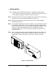
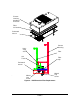
Step 1. Carefully remove the unit from the shipping carton and inspect for any damage
that may have occurred during transportation. (See Figure 1)
Step 2. Wipe down plastic bag and move unit into clean room. (Double bagging is
available upon request.)
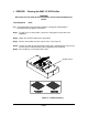
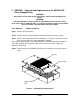
Step 3. If using rigidly supported grid (usually 2” or wider), raise unit through ceiling and
lower onto the gasketed grid. If using a flexible grid (typically supported with
wires) the unit must be secured to an overhead structure with eyebolts, s-hooks
and chain. A roll of high-density gasket has been provided for use with
ungasketed grids. Note: special size units are available to fit specific clean
room grid systems.
Step 4. Have an electrician wire the unit to the appropriate voltage (115V, 220V, 277V
AC), according to the wiring diagram in section IX and local electric codes. If
optional power cord was purchased, plug unit into a grounded receptacle.
Figure 1 – Unit Uncrating