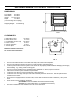
SHERWOOD INDUSTRIES IS AN ENVIRONMENTALLY RESPONSIBLE COMPANY THIS MANUAL IS PRINTED ON RECYCLED PAPER EG 28 B Vented OWNERS MANUAL By SHERWOOD INDUSTRIES WHAT TO DO IF YOU SMELL GAS • Open windows • Do not try to light any appliance. • Do not touch any electrical switch; do not use any phone in your building. • Immediately call your gas supplier from a neighbor's phone. Follow the gas supplier's instructions. • If you cannot reach your gas supplier, call the fire department.
SAFETY PRECAUTIONS FOR SAFE INSTALLATION AND OPERATIONOF YOUR "ENVIROGAS" STOVE, PLEASE, CAREFULLY READ THE FOLLOWING INFORMATION: • GENERAL • Installation and repair should be done by a qualified service person. The appliance should be inspected before use and at once least annually by a qualified service person. More frequent cleaning may be required due to excessive lint from carpeting, bedding material, etc.
TABLE OF CONTENTS Safety Precautions Code Approvals Deciding where to locate your stove Venting Installation of Log Sets and Embers Operating Instructions Maintenance and Technical Trouble Shooting Gas Line Connection Electrical Parts and Accessories Fuel Type Conversion Warranty Parts List Exploded Views Installation Data Sheet 2 3 4 6 8 9 10 11 12 13 14 15 16 17 18-19 20 CODE APPROVALS • This Vented appliance draws all of its combustion air from the dwelling and must be vented using listed B or L vent.
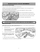
DECIDING WHERE TO LOCATE YOUR STOVE DIMENSIONS: Front Width: 22"/ 56cm Rear Width: 22"/ 56cm Height: 27-1/2"/ 70cm* Depth 19"/ 48cm (*not including vent coupling) Shipping Weight: 210 lbs/95 kg FIG. 1 CLEARANCES: A. Side wall to stove B. Rear wall to stove C. Combustible to stove Top D. Floor to stove E. Corner clearance F. Alcove depth 10"/ 25cm 4"/ 10cm 22”/ 56cm 0"/ 0cm 2"/ 5cm 48"/ 122cm Maintain sufficient clearances for service and maintenance FIG.
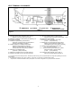
VENT TERMINAL CLEARANCES Figure 3 H= *Not to be installed above a meter/regulator assembly within 3 feet (90cm) horizontally from the center-line of the regulator I= Clearance to service regulator vent outlet [*6 feet (1.8m) minimum] J= Clearance to non-mechanical air supply inlet to building or the combustion air inlet to any other appliance [12 inches (30cm) minimum] K= Clearance to a mechanical air supply inlet [*6 feet (1.
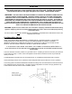
VENTING This model must have a vent opening in the rear of the unit. Confirm this and also check that the label on the right side panel door states "Vented Room Heater". WARNING: THIS APPLIANCE HAS BEEN DESIGNED TO OPERATE BY DRAWING COMBUSTION AIR AND DILUTION AIR FROM THE ROOM. THE DRAFT HOOD LOCATED IN THE SAME ATMOSPHERIC PRESSURE ZONE AS THE COMBUSTION AIR INLET TO THE APPLIANCE. IT IS ALSO DESIGNED TO DRAW ROOM AIR FOR PROPER HEAT CIRCULATION FROM THE REAR OF THE UNIT.
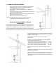
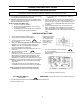
A. USING AN EXISTING CHIMNEY • • • • • Measure the height of the chimney beforehand and purchase the appropriate kit. Never attempt to over stretch a flexible liner to accommodate the height of the chimney. Any flue damper must be removed or locked permanently in the open position. The chimney must be clean, in good working order and constructed out of non-combustible materials. Make sure that all chimney clean-outs are tightly fitting and will not permit air to leak into the chimney.
INSTALLATION OF LOG SET and EMBERS INSTALLING THE GLOWING EMBERS A bag of Rock Wool embers is provided for use on the burner tray. CAUTION: Use only the type of ember material supplied with this appliance. Due to the irregular size of the ember material there may be more than required. If over time, through cleaning and servicing, these embers require replacement, contact your nearest ENVIROGAS dealer for replacement embers. Remove the ember material from the plastic bag.
OPERATING INSTRUCTIONS FOR YOUR SAFETY READ BEFORE OPERATING WARNING: IF YOU DO NOT FOLLOW THESE INSTRUCTIONS EXACTLY, A FIRE OR EXPLOSION MAY RESULT CAUSING PROPERTY DAMAGE, PERSONAL INJURY OR LOSS OF LIFE. A) This appliance is equipped with a pilot, which must be lit by • If you cannot reach your gas supplier, call the fire hand by following these instructions exactly. department.
MAINTENANCE AND TECHNICAL Annually check to ensure that your Venting system is clear. 3. Ensure the door is properly fastened after cleaning before attempting to re-light the appliance. Periodically check the pilot and burner. Check to see that all the burner ports are clean and clear. Check the pilot head for blockage. Check to ensure the pilot flame is blue with small yellow tips. TO REPLACE DOOR AND GLASS ASSEMBLY The glass in this appliance is an integral part of the door assembly.
Problem Spark will not light the pilot after repeated pressing of spark igniter Pilot will not remain lit Burners will not remain lit Flame lifting Glass fogs up Blue flames Flames are burning “dirty” or Sooting Possible Cause Defective piezo igniter Solution Check connections to igniter -If igniter connections are good but there is no spark-replace igniter Broken spark electrode -Check for broken ceramic insulation replace, electrode if broken Miss-aligned spark electrode -If spark is not arcing from
GAS LINE CONNECTION ORIFICE SIZES, PRESSURE AND BTU’S NATURAL GAS #42 dms 3.8” wc (0.95 kPa) 1.1” wc (0.27 kPa) 7.0” wc (1.74 kPa) 5” wc (1.25 kPa) 26,500 Btu/h(7.87 kW) 13,500 Btu/h(3.9 kW) 20,700 Btu/h(6.06 kW) 21,200 Btu/h(6.21 kW) Orifice size Manifold pressure. Min. Manifold pressure. Supply Pressure. Min. Supply pressure. Max. BTUH Input. Min. BTUH Input. Output fan off Output fan on PROPANE GAS #53 dms 11” wc (2.74 kPa) 2.7” wc (0.67 kPa) 12” wc (2.98 kPa) 11.5” wc (2.86 kPa) 26,500 Btu/h(7.
The ENVIROGAS EG 28.FS.BV. will operate with no external power supply. These models have a Millivolt gas control which uses the pilot flame to generate enough electricity to operate the main burner. The appliance when installed, must be electrically connected and grounded in accordance with local codes or in the absence of local codes, with the current CSA C22.1 CANADIAN ELECTRICAL CODE. Part 1, SAFETY STANDARDS FOR ELECTRICAL INSTALLATIONS, or THE NATIONAL ELECTRICAL CODE ANSI / NFPA 70 in the USA.
PARTS AND ACCESSORIES Service Parts available from your local Envirogas Dealer Burner Control Assembly Natural Gas Pilot Assembly Propane Pilot Assembly Door Bolt Relief Door Gasket Regulating Valve Piezo Igniter Burner Switch B-vent Spill switch 220° Orifice Blank Convection Blower Light Bulb Holder Light Switch (momentary) Fan Controller Log Set (with Embers) Thermocouple Embers Thermopile Door Gasket Convection Fan Sensor 120° (48°C) Accessories Gold trim Package Low Voltage Thermostat REMOVING or INS
ADJUSTING THE VENTURI • • • • Remove the ash shelf by undoing the screw at each end, pull shelf towards you. Remove one screw from the cover plate located below the ash shelf. Loosen the other screw (do not remove) swing the cover plate out of the way and tighten screw down to hold it in place. With along screwdriver rotate spring clips to open or close the shutter to the desired setting. The burner flame should be a bright yellow/orange when hot.
WARRANTY Because of our high standards Sherwood Industries Ltd. can offer a *Lifetime Warranty on all it’s gas products. Covered under this warranty are Cabinet Sides, Tops, Pedestals, Surround Panels and Chassis. These steel components are covered against manufacture’s defects for 5 years and labour for the first years and for parts only thereafter. Please refer to the warranty agreement for specific details on the coverage of your *Lifetime Warranty. Sherwood Industries Ltd.
PARTS LIST EC-001 EC-002 EC-006 EC-007 EC-009 EC-011 EC-012 EC-013 EC-014 EC-015 EC-016 EC-019 120° F CERAMIC TEMP SENSOR 220° F CERAMIC SPILL SWITCH SIT NOVA 820 NG VALVE 50% SIT NOVA 820 LP VALVE 50% THERMOCOUPLE (POST 10/00) SPARK ELECTRODE w/CABLE THERMOPILE PILOT NG w/ELECTRODE PILOT LP w/ELECTRODE FULLY ASSEMBLED PILOT NG FULLY ASSEMBLED PILOT LP PILOT ORIFICE NG EG28-108 EG28-109 EG28-116 EG28-120 EG28-121 EG28-123 EG28-124 EG28-125 EG28-126 EG28-129 EG28-130 EG28-131 FREESTANDING PEDESTAL FS PEDE
BV 4” CRIMPED FLUE PIPE 120 ° F (49° C) CERAMIC FAN TEMP SENSOR FS BV STOVE TOP EG28124 EG28-169 DV 4” FLARED FLUE PIPE EC-001 FS DV STOVE TOP EG28-126 EG28-170 CONVECTION BLOWER BV TOP BAFFLE EG28-132 DV TOP BAFFLE EC-030 EG28-131 FS FAN MOUNTING BRACKET FS CABINET SIDE PANEL EG28-304 EG28-123 WIRE CHANNEL EG28-139 DOOR MAGNET AND BRACKET 220° F (104° C) CERAMIC SPILL SWITCH EC-002 UPPER GOLD BARS 1 X 1 SIDE CABINET HINGE EG28-129 LOWER GOLD BAR EC-054 EG28-130 FS CABINET SIDE PA
FULLY ASSEMBLED PILOT PAN BURNER TOP EC-015 NG , 016 LP BURNER CONTROL ASSEMBLY COMPLETE PAINTED DOOR ASSEMBLY WITH GLASS (A+B) THERMOPILE EC-012 EG28-143 NG EG28-145 LPG EG28-099 THERMOCOUPLE VENTURI TUBE EC-009 GOLD DOOR ASSEMBLY WITH GLASS (A+B) PILOT ORIFICE EG28-101 EC-019 NG, 020 LP SPARK ELECTRODE EC-011 BURNER BRACKET GLASS RETAINER ORIFIC E BLANK GAS TRAY TOP AND SIDES EC 022 GLASS EXTRUSIONS DOOR LATCH BOLT EC-059 DOOR LATCH STRIP FS LIGHT BULB HOLDER EC-031 S.I.
INSTALLATION DATA SHEET The following information must be recorded by the installer for warranty purposes and future reference.