
Instructions / Assembly

READ ALL THE INSTRUCTIONS
TOOLS & MATERIALS REQUIRED
Before assembling your lighting fixture, refer to the “ELECTRICAL
CONNECTIONS” section. If you feel you do not have electrical wiring
experience, refer to a do-it-yourself wiring handbook or have your fixture
installed by a qualified licensed electrician.
QUESTIONS? CALL TOLL FREE
1-855-573-6156
INSTALLATION & OPERATION INSTRUCTIONS –
6” REMODEL IC RECESSED LIGHTING HOUSING WITH SLIDE-N-LOC™ FEATURE
ALL RIGHTS RESERVED. COPYRIGHT ENVIROLITE 2019
Ladder, BX or NM Cable, BX Cable Connectors (if necessary), Keyhole
Saw, Flathead Screwdriver, Hammer, Insulated Pliers, Pencil, UL Listed
Electrical Tape.
MODEL EVRH7ICRAT
CAUTION
BEFORE YOU BEGIN
1. To ensure the success of the installation, be sure to read these
instructions and review the diagrams thoroughly before beginning.
2. All electrical connections must be in accordance with local code,
ordinances. If you are unfamiliar with methods of installing electrical
wiring, secure the services of a qualified licensed electrician.
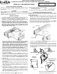
3. IMPORTANT: This fixture is either an IC type or Non-IC type fixture.
A Non-IC type fixture is intended for use in recessed cavities or
suspended ceilings where the recessed portions of the fixture,
other than at points of support, must be a minimum of 3” from
thermal insulation and at least 1/2” from combustible material (e.g.
ceiling joists, floor boards). (Fig. 1)
CEILING INSTALLATION
1. Choose the location for the fixture, taking into consideration the 6” depth
clearance, the location of ceiling joists and the accessibility for the
electrical supply. For Non-IC models, a 1/2” clearance from the joists and
floor boards and 3” clearance from insulation must also be considered.
Mark the selected location using the provided template.
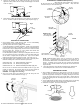
2. Using a keyhole saw make the hole in the ceiling surface. (Fig. 2) (Note:
Be sure not to make the hole any larger than specified by the template.
An oversized hole may not allow for proper installation.)
An IC type fixture may also be used in recessed cavities.
However, it may come in direct contact with thermal insulation.
Any part of the fixture may be covered by thermal insulation.
Please review the packaging or the product labels to determine
your fixture type. (Note: A housing with a white-painted can is a
Non-IC type fixture and one with a bare-metal can is an IC type
fixture.) If you have determined that your housing is a Non-IC
type, be sure to space any insulation away a minimum of 3”.
4. This fixture is thermally protected. A blinking light indicates thermal
insulation has been placed too close to the fixture, or an incorrect lamp
has been installed, or heat from another source is affecting the fixture.
Always double check your intended locations prior to making holes in
the ceiling for installation.
5. This fixture is a remodel type fixture. A remodel type fixture is for
applications where there is an existing ceiling surface, such as drywall,
and the ceiling joists are not accessible. For applications where there
is no ceiling surface and the ceiling joists are accessible, such as when
a home is under new construction, a new-construction type fixture
should be used.
6. Note: This remodel type fixture uses special C-clips to secure itself to
the ceiling material. The C-clips are designed for surfaces that are
between 3/8” and 5/8” thick. These C-clips will not work on surfaces
thicker than 5/8”.
7. Before starting the installation, disconnect the power by turning off the
circuit breaker or by removing the appropriate fuse at the fuse box.
Turning the power off by using the light switch is not sufficient to
prevent electrical shock.
8. Check if the power source is suitable for the added electrical load.
Power should be supplied by a 120 volt, 60 Hz single circuit. A
standard 120 volt, 15 amp branch circuit is designed to carry a
maximum load of 1800 watts. We recommend that the total wattage of
all the lights and appliances, on that circuit, not exceed 80% or 1440
watts, of the maximum electrical capacity.
UNPACK THE FIXTURE
Check the contents of the box. You should receive:
• 1 – Housing (can, junction box)
• 1 - Trim assembly (kits only)
PREPARING AND MOUNTING THE FIXTURE
NOTE: First turn off electricity at the circuit breaker or the fuse box. Turning
the power off by using a wall switch is not sufficient to prevent electrical shock.
• 1 – Template
• 3 – C-clips
Note: Hanger bars are not provided. They must be purchased separately.
Fig. 2
3. Proceed to the “ELECTRICAL CONNECTIONS” section to connect the
housing to the home / building electrical supply.
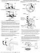
4. Attach the provided C-clips onto the inside surface of the can by inserting
the ends into the provided T-slots, as shown. Feed the junction box
through the ceiling hole, followed by the can. Allow the C-clips to hang
on the inside surface of the can until the can is completely inserted into
the ceiling. (Fig. 3)
Ceiling joist
Ceiling surface
Fig. 3
C-clips
Can
Cross-section view of
C-clip attachment to T-
slot of can
Ceiling
Junction
Box
T-slot
Side View
of Housing
Note: The T-shaped end of the C-clip should be
inserted into the bottom part of the T-slot
• 3 – “Quick-Connect”
Wire Connectors