
Instructions / Assembly

ALL RIGHTS RESERVED. COPYRIGHT ENVIROLITE 2019
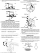
When using the “quick-connect” wire connectors,
be sure that there are no loose/exposed wire strands. Wrap each wire
connection using UL Listed electrical tape.
Rectangular
Knockout
NM Cable
(ROMEX)
Junction
box door
Flathead
Screwdriver
FIG. 8
“Quick-Connect”
wire connectors
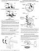
1. After installing and finishing the ceiling surface, insert the trim into the
housing. Insert the tip of a pencil into the loop of one of the coil springs.
Push the loop upward, stretching the coil spring, inserting the hook into
one of the keyhole slots locate on the socket plate. Repeat with the
remaining coil spring with the remaining keyhole slot to secure the trim in
place. (FIG. 9)
2. Screw a light bulb into the lamp socket and making sure to use the lamp
type an wattage specified on the housing’s lamp replacement label.
3. Installation is complete. Restore electrical power.
FIG. 9
Pry out
knockout
SLIDE-N-LOC™ -
Slide NM cable
into locking slot
5. Close the junction box door until the metal latch snaps, making sure
that all wiring and wire connectors are contained within the box.
FIG. 7
Round
Knockout
Coil Spring
Loop
Hook
Trim
Housing
Keyhole
Slot
NOTE: Additional lighting fixtures may be connected to the fixture’s
junction box. Several knockouts are provided on the junction box to
accommodate additional BX or NM cables intended to connect to other
fixtures. A marking on the junction box door specifies the maximum
number of wires and the maximum wire gauge that can be inserted into
the junction box.
ELECTRICAL CONNECTIONS (CONT.)
TRIM INSTALLATION
ELECTRICAL CONNECTIONS
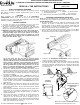
1. Using flexible conduit or NM (Romex) cable, run the house/building
electrical wiring to recessed fixture locations.
2. Open the junction box’s door by pulling on its metal tab.
A. FOR ELECTRICAL FLEXIBLE CONDUIT - Break off the appropriate
sized round knockout using a screwdriver. Feed the conduit through the
knockout hole, using an appropriately sized connector to lock the conduit
into the junction box. Remove 3” of the conduit metal sheath and
remove the plastic or paper over-wrap. (Fig. 7)
B. FOR NM (Romex) CABLE – Bend up a rectangular tab locate on the
top of the junction box using a screwdriver. Insert the NM-B cable into
the slot until 6” of length enters the junction box. Strip 3” of the cable’s
plastic sheath and remove the paper over-wrap. (See inset of Fig. 7)
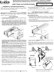
3. Strip approximately 3/8” of insulation from the ends of all supply wires.
Make the following wire connections within the junction box:
WHITE fixture wire TO WHITE (NEUTRAL) supply wire
BLACK fixture wire TO BLACK (HOT) supply wire
GREEN fixture wire TO GREEN OR BARE (GROUND) supply wire
Be sure to use UL Listed wire connectors suitable for the size, type, and
number of conductors. Be sure that there are not any loose strands or
loose wire. Secure wire connectors with UL Listed electrical tape.
WARNING - Use supply wires rated 90°C.
4. Close the junction box’s door making sure that all wiring and wire
connectors are contained within the box. (Fig. 7)
5. Push the can complete into the ceiling until the lip of the can is flush
against the ceiling. Make sure the C-clips are still hanging on the inside
of the can. (Fig. 4)
6. Push all three ceiling clips through the T-slots until they are outside of
the can. Continue to push the clips until they snap into place. (Fig. 5)
C-clip
Fig. 4
Fig. 5
C-clip
Hand
Can
Ceiling
Ceiling
Junction
box door
Knockout