
Installation Guide

3. Connect the fixture ground wire and the supply ground wire together using a wire nut.
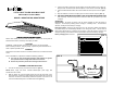
Wrap the wire connections with electrical tape for a more secure connection. [FIG. 2]
4. Insert the black ON/OFF switch wire into the black side of the quick connector. [FIG.
2]
5. Align the reflector an turn the lock pins (A) to secure the reflector in place. [FIG. 1]
6
Line
up
the
T
8
tube
with
the
end
marked
“
L
&
N
”
into
the
side
where
the
arrow
on
the
4-FT 6-LIGHT T8 LED HIGH BAY LIGHT
WITH 6 DLC FLEX TUBES
6
.
Line
up
the
T
8
tube
with
the
end
marked
L
&
N
into
the
side
where
the
arrow
on
the
label is pointing. Insert the lamp into the socket and rotate 90° (a quarter turn) to lock
it in place.
OPERATION
Normal Mode: AC power is present. The AC driver operates the LED T8 lamps as
designed. The emergency battery pack is charging in a standby mode. The test button
will be lit, showing that the battery is charging
WITH
6
DLC
FLEX
TUBES
MODEL: HBA6T18XXB, HBA6T35XXB
INSTALLATION
INSTRUCTIONS
Emergency Mode: When the AC power goes out, the emergency battery pack detects
the power outage and automatically switches to the emergency mode. One of LED T8
lamps will be illuminated for a minimum of 90 minutes. When AC power is restored, the
emergency battery pack switches back to Normal Mode and resume battery charging.
Battery Charging Time: 24 hours
FIG. 1
INSTALLATION
INSTRUCTIONS
Please read carefully and save these instructions. Failure to do so may lead to
electrical shock or fire, which may cause injury or death.
CAUTION
WARNING – RISK OF FIRE: Turn off the main power at the circuit breaker
before installing the fixture, changing lamps, or performing other maintenance in
order to prevent possible shock
order
to
prevent
possible
shock
.
GENERAL
All electrical connections must be in accordance with local, and national electrical
codes.
Prior to installation it is important to follow the following guidelines:
A. Use only the type of tube light specified, with wattage not greater
than
specified
on
the
wattage
label
found
on
the
fixture
FIG. 2
than
specified
on
the
wattage
label
found
on
the
fixture
.
B. Remove all protective plastic film covering from the fixture.
ASSEMBLY AND INSTALLATION
1. Turn the four lock pins (A) and remove the reflector. [FIG. 1]
NOTE
Btt
l
i
d
tt
it td
l
d
Ground Wires
Battery Wires
Uninterrupted
Power Supply
NOTE
:
B
a
tt
er
y
supp
ly
w
i
re nee
ds
cons
t
an
t
un
i
n
t
errup
t
e
d
p
ower supp
ly
an
d
should not be on a switch.
2. With the power off, insert the black supply wire into the black side of the
quick connector. Connect the white supply wire to the white side of the quick
connector. Connect the white battery connectors together. Use a wire nut to
connect the black battery wire to the black fixture wire. [FIG. 2]
Black Battery Wire
Black & White Supply Wires
Black &
White Wire