L9CMonitor Service Manual for the Envision EN9410 Feb, 18th, 2005 Revision: 1A Issued By: Checked By: _____________________________________________________________________________ ____ The release of this document is under control by the company. Any extra copy of this document must be written permission by the product manager.
L9CMonitor _____________________________________________________________________________ ____ - Quanta Confidential – History Page Reversion 1A Date 2/18/2005 ST 1 Remark Released.
L9CMonitor Content Chapter A. WARNING B. SAFETY PRECAUTIONS 1. DIMENSIONS 2. GENERAL INFORMATION 3. SPECIFICATIONS 4. THEORY OF OPERATION 5. CONTROL LOCATION 6. NECESSARY EQUIPMENT LIST 7. BLOCK DIAGRAM 8. CONDUCTOR VIEW 9. SCHEMATIC DIAGRAM 10. EXPLODED VIEW 11. TROUBLE SHOOTING HINTS 12. REPLACEMENT PARTS LIST 13.
L9CMonitor WARNING This service information is designed for experienced repair technicians only and is not designed for use by the general public It does not contain warnings or cautions to advise non-technical individuals of potential dangers in attempting to service a product. Products powered by electricity should be serviced or repaired only by experienced professional technicians.
L9CMonitor SAFETY PRECAUTIONS 1. CAUTION: No modification of any circuit should be attempted. Service work should only be performed after you are thorough familiar with all of the following safety checks and servicing guide lines. 2. SAFETY CHECK Care should be taken while servicing this LCD display. Because the high voltage is used in the inverter circuit. These voltages are exposed in such areas as the associated transformer circuits. 3.
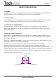
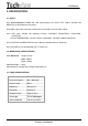
L9CMonitor 1. DIMENSIONS (Unit:mm) 1.1 Front View (ID1) 1.
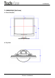
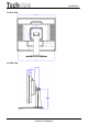
L9CMonitor 1.3 Rear View 1.
L9CMonitor 2. GENERAL INFORMATION 2.1. OUTLINE This monitor is 19" multi-scan color LCD display with the following features OSD (on screen display) control allows easy user adjustment . Power saving function, which helps saving energy, is also one of the highlights of this model. 2.2. FEATURES 2.2.1 Power Saving Built in Power Saving function based on VESA-DMPS standard. Power energy shall be saved by controlling the circuit in accordance with power save signal from computer. 2.2.
L9CMonitor 3. SPECIFICATION 3.1. Outline 3.1.1 Front Indication: POWER SW, LED (Green/Amber), UP, Down, LEFT, RIGHT, Set/Auto and MENU key are located on the front panel. 3.1.2 Video signal cable connector, and DC inlet are located on the backside cabinet. 3.1.3 OSD menu includes the following function. CONTRAST, BRIGHTNESS, H.POSITION, V.POSITION COLOR-TEMPERATURE, CLOCK, PHASE, LANGUAGE, VOLUME, POWER-ON-RECALL 3.1.4 CONTRAST and BRIGHTNESS can be directly controlled with UP / Down key. 3.1.
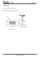
L9CMonitor 3.4. CONNECTORS 3.4.1 AC inlet : CEE22 typed connector 3.4.2 Attached video signal cable connector x 1 Shell 1 2 3 4 5 10 6 11 12 13 14 15 Figure 3.4 Pin Signal Name 1 2 3 4 5 6 7 8 9 10 11 12 13 14 15 Red video Green video Blue video Ground Ground Red ground Green return Blue return N/C Ground Ground SDA (serial data) Hsync Vsync (VCLK) SCL (serial clock) Signal cable input connector.
L9CMonitor 3.5. ELECTRICAL SPECIFICATIONS 3.5.1 Standard conditions Display area (HxV) 378.3*303mm Video signal level 0.7 Vpp Contrast Max. Brightness Max. Ambient Temperature 25 +/- 5 C degrees Input voltage Universal power Warming up time At least 30 1280 x 1024 Display mode 3.5.2 POWER 3.5.2.1 Power supply AC-DC adapter Input voltage Input current Frequency range 100-240V Max. 0.
L9CMonitor 3.5.3 Signal level and input impedance 3.5.3.1 Video Signal level This LCD display is adjusted at the factory using 0,7 Vp-p Video signal. 3.5.3.2 Sync Signal level H/V Separate: TTL level 3.5.3.3 Input impedance Video input: 75 ohms +/- 1% Sync input: > 1 k ohms 3.5.4 Display Area Display area: 378.
L9CMonitor 3.5.5 Preset Timings The product has 32 memory modes in total. 15 modes are preset and 17 modes are user definable. Format Pixel Clock(MHz) 1 2 640x350@70Hz 720x400@70Hz 3 4 5 640X480@6 640x480@7 640x480@7 0Hz 2Hz 5Hz 25.176 28.320 25.175 31.500 31.500 P N N N N Frequency(KHz) 31.470 31.467 31.469 37.861 37.
L9CMonitor 6 7 8 9 800x600@56Hz 800x600@60Hz 800x600@72Hz 800x600@75Hz 36.000 40.000 50.000 49.500 P P P P Frequency(KHz) 35.156 37.879 48.077 46.875 Total Time(pixels) 1024 1056 1040 1056 Display Time(pixels) 800 800 800 800 72 128 120 80 Back Porch(pixels) 128 88 64 160 Front Porch(pixels) 24 40 56 16 Blank time(pixels) 224 256 240 256 P P P P 56.250 60.317 72.188 75.
L9CMonitor 10 Format Pixel Clock(MHz) 1024x768@60Hz 11 12 1024X768@70Hz 1024X768@72Hz 13 1024X768@75Hz 65.00 75.000 78.000 78.750 N N N P Frequency(KHz) 48.363 56.476 58.036 60.023 Total Time(pixels) 1344 1328 1344 1312 Display Time(pixels) 1024 1024 1024 Horizontal Sync Polarity 1024 Sync Width(pixels) 136 136 132 96 Back Porch(pixels) 160 144 164 176 Front Porch(pixels) 24 24 24 16 Blank time(pixels) 320 304 320 288 N N N P 60.004 70.069 71.916 75.
L9CMonitor 14 15 1280x1024@60Hz 1280x1024@75Hz 108.000 135.000 P P Frequency(KHz) 63.981 79.976 Total Time(pixels) 1688 1688 Display Time(pixels) 1280 1280 Sync Width(pixels) 112 144 Back Porch(pixels) 248 248 Front Porch(pixels) 48 16 Blank time(pixels) 408 408 P P 60.020 75.
L9CMonitor 3.5.6 General performance 3.5.6.1 Maximum pixel clock 135 MHz 3.5.6.2 Maximum luminance Test conditions: 100% all white pattern, brightness set to Maximum typical: 250 cd/m2 min : 200cd/m2 3.5.6.3 Brightness variation Value 75 % Variation (C / A x 100) Conditions Display image: Full white Brightness : Maximum Contrast : Maximum A: Luminance at center position 3.5.6.
L9CMonitor Transport (packed) Temperature: Humidity: Height: -20°C - +60° C 8% - 95% non–condensing 12000 m L9C service manual Page18 of 48 - Techview Confidential -
L9CMonitor 3.7. REGULATORY STANDARDS 3.7.1 Safety standards This monitor applies to various safety & EMI standards May refer to the logo label 3.7.2 EMC standards FCC part 15,subpart B , class-B (EMV) CE marking 3.8. OTHERS UL, cUL, 3.9. P0WER CORD Northern Hemisphere Version: UL / CSA approved power cord. European: VDE approved power cord. 3.10. SIGNAL CABLE Signal cable with Mini D-Sub 15P connectors. Length: 1.8 meter. 3.11.
L9CMonitor 4. THEORY OF OPERATION This section describes the function of the LCD monitor per functional block. L9EA monitor includes MB Board (including audio board function inside), power board and button board. 4.1 MB BOARD The MB board is a two-layer, single-landed design with ground and ground planes provided.
L9CMonitor d) OSD : The TSU16AK has a fully programmable, high-quality OSD controller. The on-chip Static RAM (256 different fonts at size of 12X18) stores the cell map and the cell definitions. e) Inverter Brightness control (PWM0) (Pin 73) The TSU16AK has one PWM output PWM0(Pin73) to control Inverter Brightness Range. f) Panel LVDS interface (Pin 102~103, Pin106~113, Pin118~125, Pin128, Pin1) The TSU16AK driver interface is highly programmable. It supports LVDS port for panel. 4.1.
L9CMonitor 4.2 Power Module The power module includes an Inverter and Power regulator. The electrical specification described as following: 4.2.1 Power Characteristics. Input Rated Input Voltage 90~240 Vac,50/60Hz Operation Input Voltage Range 90~264 Vac,47~63Hz Max Input AC Current < 1.2A Efficiency 12Vdc load 3.5A Brightness Voltage from 0.3~3Vdc ON/OFF Voltage : High(3.3Vdc)/Low(0Vdc) Output Brightness Voltage(Vadj) 0.3Vdc(Max) ~ 3Vdc(Min) On/Off Voltage High(3.
L9C Monitor 5 CONTROL LOCATION Button Define 1 OSD Menu Trigger OSD Main Menu / Clear OSD 2 UP 1. Select OSD Main Menu Item 2. Trigger Brightness/Contrast Menu. 3 DOWN 1. Select OSD Main Menu Item 2. Trigger Brightness/Contrast Menu. 4 POWER 5 LEFT 1. Decrease Menu Item value 2. Trigger Volume Menu. 6 RIGHT 1. Increase Menu Item value 2. Trigger Volume Menu. 7 SELECT/ AUTO Switch Power ON/OFF 1. Switch OSD Main Menu focus status. 2. Perform Auto configuration.
L9C Monitor LED Status Color Green Status Description Normal status Enter Sleep Mode status or use “Power + Auto” key Amber enter factory mode L9C service manual Page -Techview Confidential - 24of 48
L9C Monitor Dialog Overview OSD Main Menu When user press the Menu key under none OSD status will trigger this menu appear for detail parameters adjust. This menu will display about 20 seconds if no one press other key, otherwise will refresh display time length. Brightness/Contrast Menu When user press the Up or Down keys under none OSD status will trigger this menu appear for Brightness and Contrast adjust. This menu will display about 20 seconds.
L9C Monitor Auto Configuration When user press the select/Auto key under none OSD status will trigger this dialog appear and perform Auto Configuration procedure. Mode Information When Display timing changed this dialog will appear about 3 seconds. And this feature only enable when “Information” indicate On in OSD’s other page of main menu. No Signal When user does not support the video signal from the cable this dialog will appear about 10 seconds. And then enter the Sleep mode.
L9C Monitor Out Of Range When user input the video signal out of spec this dialog will appear about 10 seconds. And then enter the Sleep mode. OSD Main Menu Brightness & Contrast Adjustment Brightness (Up&Down): Adjust the brightness of the display. Contrast (Left&Right): Adjust the difference between the light and dark areas.
L9C Monitor Tracking Adjustment CLOCK: Adjust to minimize any vertical bars or stripes visible on the screen background. The horizontal screen size will also change. PHASE: Adjust to remove any horizontal distortion, and clear or sharpen the image of characters. Position Adjustment V-Position: Adjust the vertical position of the picture. H-Position: Adjust the horizontal position of the picture.
L9C Monitor Color Adjustment There are four items for color adjustment: 9300K: Bluish white 6500K: Reddish white User defined: Red, Green, Blue. Adjust to set your own color level. Other LANGUAGE: Multi- Language selection OSD POSITION: Adjust the OSD window position on the screen. INFORMATION: Display Information Dialog or not when input timing changed. RESET: Recall to factory settings.
L9C Monitor Factory1 Adjustment This page only visible in factory mode R,G,B OFFSET : Adjust current RGB cut off level R,G,B GAIN : Adjust current RGB Driver value. SSPLL and SSMOD : Adjust chip set internal frequency spread effect for EMI testing.
L9C Monitor Factory2 Adjustment This page only visible in factory mode AUTO BURN : Use the chip set internal pattern for hot running monitor panel and inverter. AUTO COLOR : Perform Auto Balance measurement . AUTO COLOR 1 : Perform Auto Balance measurement by chip set internal signal. And reference these values to initial all other color temperature detail parameters. COLOR UPDATE : Force presently R,G,B offset and gain parameters update to currently temperature memory address.
L9C Monitor 6.
L9C Monitor 7. BLOCK DIAGRAM 7.1 Power module To Panel lamp Inverter Output Voltage Output 12V/3.
L9C Monitor 7.
L9C Monitor 8.
L9C Monitor Power Board Silkscreen L9C service manual Page -Techview Confidential - 36of 48
L9C Monitor Button Board Silkscreen L9C service manual Page -Techview Confidential - 37of 48
L9C Monitor 9.
L9C Monitor L9C service manual Page -Techview Confidential - 39of 48
L9C Monitor L9C service manual Page -Techview Confidential - 40of 48
L9C Monitor L9C service manual Page -Techview Confidential - 41of 48
L9C Monitor L9C service manual Page -Techview Confidential - 42of 48
L9C Monitor Power Board Circuit L9C service manual Page -Techview Confidential - 43of 48
L9C Monitor L9C service manual Page -Techview Confidential - 44of 48
L9C Monitor 10.
L9C Monitor 11 TROUBLE SHOOTING HINTS 1.
L9C Monitor 2.No Characters , Missing one color No Characters or Missing one Check CN6 12V Output NO Change Power Board OK Check L33 , 5V Output NO Check or Change U21,Q13,Q17 OK Check L34 , 2.5V output NO Check or Change U22 Change Power Board OK Check L31 , 3.3V output Check Inverter NO NO Check or Change U23 OK From Power Check CN9 to Panel Signal Output board OK? OK NO Check X’Tal 11.059Mhz and 14.
L9C Monitor 12. REPLACEMENT PARTS LIST( See appendix) 13.Auto White Balance Procedure 1 Connect signal to monitor. The display signal need contain real black and full white. 2 Press "Auto" button(don't release) when power ON(LED display Amber). 3 Press OSD select FACTORY 2, Auto Color, RUN(For AD converter calibration on R, G and B gain, offset). 4 5 Select Color Update, RUN.