SMT inductors SIMID series, SIMID 1812-T Series/Type: B82432T Date: October 2012 Data Sheet ¤ EPCOS AG 2012. Reproduction, publication and dissemination of this publication, enclosures hereto and the information contained therein without EPCOS’ prior express consent is prohibited.
SMT inductors, SIMID series B82432T SIMID 1812-T Size 1812 (EIA) or 4532 (IEC) Rated inductance 1 ... 1000 μH Rated current 70 ...
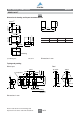
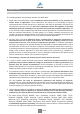
SMT inductors, SIMID series B82432T SIMID 1812-T Dimensional drawing and layout recommendation 2.6±0.11) A 0.5±0.11) B C D B IND0053-6 3.2±0.2 0.6 min.1) 4.5±0.2 0.15 max. A B C D 3.6 1.3 3.2 5.8 3.2±0.2 Marking 1) Soldering area Dimensions in mm IND0083-T-E Taping and packing Reel 12±0.3 2±0.05 _0 12.4 +1.5 <_ 4.1 1.6±0.1 8±0.1 62±1.
SMT inductors, SIMID series B82432T SIMID 1812-T Technical data and measuring conditions Rated inductance LR Measured with impedance analyzer Agilent 4294A at frequency fL, 0.
SMT inductors, SIMID series B82432T SIMID 1812-T Characteristics and ordering codes Tolerance Qmin Ordering code 1) fL ; fQ IR Rmax fres,min MHz mA : MHz 10 2.52 650 0.35 25 B82432T1103K000 12 10 2.52 630 0.45 23 B82432T1123K000 15 10 2.52 600 0.50 20 B82432T1153K000 18 10 2.52 550 0.60 18 B82432T1183K000 22 10 2.52 450 0.70 15 B82432T1223K000 27 10 2.52 430 1.00 14 B82432T1273K000 33 10 2.52 400 1.20 13 B82432T1333K000 39 10 2.52 380 1.
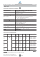
SMT inductors, SIMID series B82432T SIMID 1812-T Impedance |Z| versus frequency f measured with impedance analyzer Agilent E4991A, typical values at +20 °C Inductance L versus DC load current IDC measured with LCR meter Agilent 4285A, typical values at +20 °C IND0084-2 10 6 Ω B82432T |Z | L 10 5 10 3 10 4 10 2 10 3 10 1 1000 μH 100 μH 10 μH 1 μH 10 2 10 1 6 10 10 7 10 8 10 9 Q factor versus frequency f measured with impedance analyzer Agilent E4991A, typical values at +20 °C 100 μH
Cautions and warnings ■ Please note the recommendations in our Inductors data book (latest edition) and in the data sheets. – Particular attention should be paid to the derating curves given there. – The soldering conditions should also be observed. Temperatures quoted in relation to wave soldering refer to the pin, not the housing.
Important notes The following applies to all products named in this publication: 1. Some parts of this publication contain statements about the suitability of our products for certain areas of application. These statements are based on our knowledge of typical requirements that are often placed on our products in the areas of application concerned.