
Datasheet

(4/57)
20190828 / mlcc_commercial_general_en.fm
Please be sure to request delivery specifications that provide further details on the features and specifications of the products for proper and safe use.
Please note that the contents may change without any prior notice due to reasons such as upgrading.
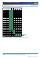
MULTILAYER CERAMIC CHIP CAPACITORS
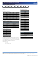
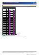
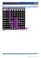
■CATALOG NUMBER CONSTRUCTION
(1) Series
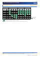
(2) Dimensions L x W (mm)
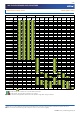
(3) Temperature characteristics
(4) Rated voltage (DC)
(5) Nominal capacitance (pF)
The capacitance is expressed in three digit codes and in units of
pico Farads (pF). The first and second digits identify the first and
second significant figures of the capacitance. The third digit identi-
fies the multiplier. R designates a decimal point.
(Example)0R5 = 0.5pF
101 = 100pF
225 = 2,200,000pF = 2.2µF
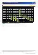
(6) Capacitance tolerance
(7) Thickness
(8) Packaging style
(9) Special reserved code
C 3216 X5R 1A 107 M 160 A C
(1) (2) (3) (4) (5) (6) (7) (8) (9)
Code EIA Length Width Te r m i n a l w idth
0402 CC01005 0.40 0.20 0.07
0603 CC0201 0.60 0.30 0.10
1005 CC0402 1.00 0.50 0.10
1608 CC0603 1.60 0.80 0.20
2012 CC0805 2.00 1.25 0.20
3216 CC1206 3.20 1.60 0.20
3225 CC1210 3.20 2.50 0.20
4532 CC1812 4.50 3.20 0.20
5750 CC2220 5.70 5.00 0.20
Temperature
characteristics
Temperature coefficient
or capacitance change
Temperature range
CH 0±60 ppm/°C –25 to +85°C
C0G 0±30 ppm/°C –55 to +125°C
JB ±10% –25 to +85°C
X5R ±15% –55 to +85°C
X6S ±22% –55 to +105°C
X7R ±15% –55 to +125°C
X7S ±22% –55 to +125°C
Code Voltage (DC)
0G 4V
0J 6.3V
1A 10V
1C 16V
1E 25V
1V 35V
1H 50V
1N 75V
Code Tolera nce
B ±0.10pF
C ±0.25pF
D ±0.50pF
F±1%
G±2%
J±5%
K ±10%
M ±20%
Code Thickness
020 0.20 mm
030 0.30 mm
050 0.50 mm
060 0.60 mm
080 0.80 mm
085 0.85 mm
115 1.15 mm
125 1.25 mm
130 1.30 mm
160 1.60 mm
200 2.00 mm
230 2.30 mm
250 2.50 mm
280 2.80 mm
320 3.20 mm
Code Style
A 178mm reel, 4mm pitch
B 178mm reel, 2mm pitch
K 178mm reel, 8mm pitch
Code Description
A, B, C TDK internal code