
User manual

Stand: Juni 2009
Z 319 engl.
3
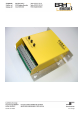
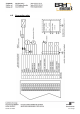
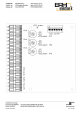
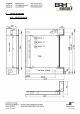
1. Brief instruction DLR 24/xx - 466 with 19-pin spring clamp terminal
1. Select modes:
• put jumper 1 on 1-2 for internal reference value (potentiometer 1) or on 2-3 for
external reference.
• put jumper 2 on 1-2 for reference value max. 5V (important for internal
reference value) or on 2-3 for 10V target value input.
• put jumper 3 on 1-2 for 12V motor or on 2-3 for 24V motor.
• put DIP switch 1 and 2 ON for inverted enables (no need of connecting terminal
15, 16 und 18)
• put DIP switch 3 to 8 Off
2. Turn potentiometer 2 (Imax) for current limitation to the right position.
3. Potentiometer 3 (IxR) compensation to left position.
4. Connection of the control wires see Connection plan, page 5.
5. Connect DC motor to terminals 3 and 4.
6. Connect power supply to terminal 1 Plus (ca. 10 – 36V DC), on terminal 2 GND.
7. Now turn on power supply.
8. LED green (power on) illuminates on the pcb.
9. With potentiometer 1 (n ref) the target value for motor speed can be adjust from 0
to 100%, if jumper 1 was put on 1-2.
10. Motor direction can be changed witch a voltage (5 – 36V DC) on terminal 19 (e.g.
bridge from clamp 17 to 19)