
User manual


Stand: Juni 2009
Z 319 engl.
5
3. Technical data
type
Supply Voltage
Armature voltage
U
A
Armature
current I
N
Mechanical power
P
ab
DLR 24/ 05 10-36V DC 0 - 12/24V DC 0 - 5A approx. 75W
DLR 24/ 10 10-36V DC 0 - 12/24V DC 0 - 10A approx. 150W
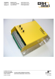
Variants: DLR 24/xx/P: screw mounting
DLR 24/xx/M: screw mounting or mounting rail 35mm
DLR 24/xx/G: screw mounting or mounting rail
35mm with yellow cover
Protection: external fuse: DLR 24/ 5 5AT
DLR 24/ 10 10AT
Environment temperature: 5° to 45°C
Relative air humidity: 18% to 85%
Control range: up to 1 : 30
Speed control through EMF control with I x R compensation
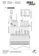
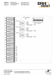
4. Connection
4.1 Control connections
ref. Speed value: terminal 11: 5V DC
terminal 12: wiper external potentiometer (10kOhm)
terminal 13: GND
Controller enable 1: terminal 15: Input 5-36V DC
Controller enable 2: terminal 16: Input 5-36V DC
ref. Speed enable: terminal 18: Input 5-36V DC
Motor direction: terminal 19: Input 5-36V DC
Output 1 (BTB): terminal 9: turns on voltage 10-36V DC (<50mA), when
the controller is ready
Output 2 (Overload): terminal 10: turns on voltage 10-36V DC (<50mA), when
the current is longer than 3 sec. on the current
limit. Resetable by select 0V ref. speed value or
disable ref. Speed enable