
Service manual
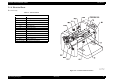


Table Of Contents
- EPSON EPL-6200/EPL-6200L
- Contents
- Product Description
- 1.1 Outline
- 1.2 Basic Specifications
- 1.2.1 Process Specifications
- 1.2.2 Printer Basic Specifications
- 1.2.3 Paper Specification
- 1.2.4 Reliability, Durability, Serviceability
- 1.2.5 Operating Conditions (Including Consumables)
- 1.2.6 Storage and Transport of the Printer Main Unit and Optional Products (Consumables Packaged)
- 1.2.7 Electrical Features
- 1.2.8 Compliance with Standards and Regulations
- 1.2.9 Consumable Components
- 1.3 External Appearance and Parts Name
- 1.4 Controller Specification
- 1.5 Control Panel (EPL-6200)
- 1.6 Control Panel (EPL-6200L)
- 1.7 RAM Expansion
- 1.8 System Requirements (Only for EPL-6200L)
- 1.9 Paper Feed Specifications (Only for EPL-6200L)
- 1.10 Notes on Operation
- 1.11 Status Sheet
- 1.12 Ambient Conditions
- 1.13 Differences in Specifications between Intended Markets
- 1.14 Notes on Installation of Optional Units
- Operating Principles
- 2.1 Overview
- 2.2 Description of Mechanisms
- 2.3 Operating Principles of Electric Circuitry
- Troubleshooting
- 3.1 Overview
- 3.2 Troubleshooting When There is Error Display
- 3.2.1 Fuser warming up problem
- 3.2.2 Fan problem
- 3.2.3 Polygon Motor Error
- 3.2.4 Laser problem
- 3.2.5 High voltage circuit problem
- 3.2.6 Fuser high temperature problem
- 3.2.7 CPU Error
- 3.2.8 Engine Communication Error
- 3.2.9 Fuser low temperature problem
- 3.2.10 Standard RAM Error
- 3.2.11 RAM Error (Slot 0)
- 3.2.12 ROM Checksum Error (Font)
- 3.2.13 ROM Checksum Error (Program)
- 3.2.14 Option ROM Error
- 3.2.15 EEPROM Error
- 3.2.16 Engine Initialization Error
- 3.2.17 Other Hardware Error
- 3.2.18 Software Error
- 3.3 Troubleshooting for Paper Jam
- 3.4 Troubleshooting for Abnormal Operations
- 3.5 Troubleshooting for Electrical Parts
- 3.6 Troubleshooting for Print Quality Problems
- Disassembly and Assembly
- Adjustment
- Maintenance
- Appendix
EPSON EPL-6200/EPL-6200L Revision A
Operating Principles Description of Mechanisms 79
2.2.3.2 OPC Drum
An OPC (Organic Photo Conductor) is used.
This photoconductor is of a laminate type consisting of a carrier generation layer and
an electric charge retaining layer applied onto an aluminum base (cylinder).
(See “Figure 2-14”)
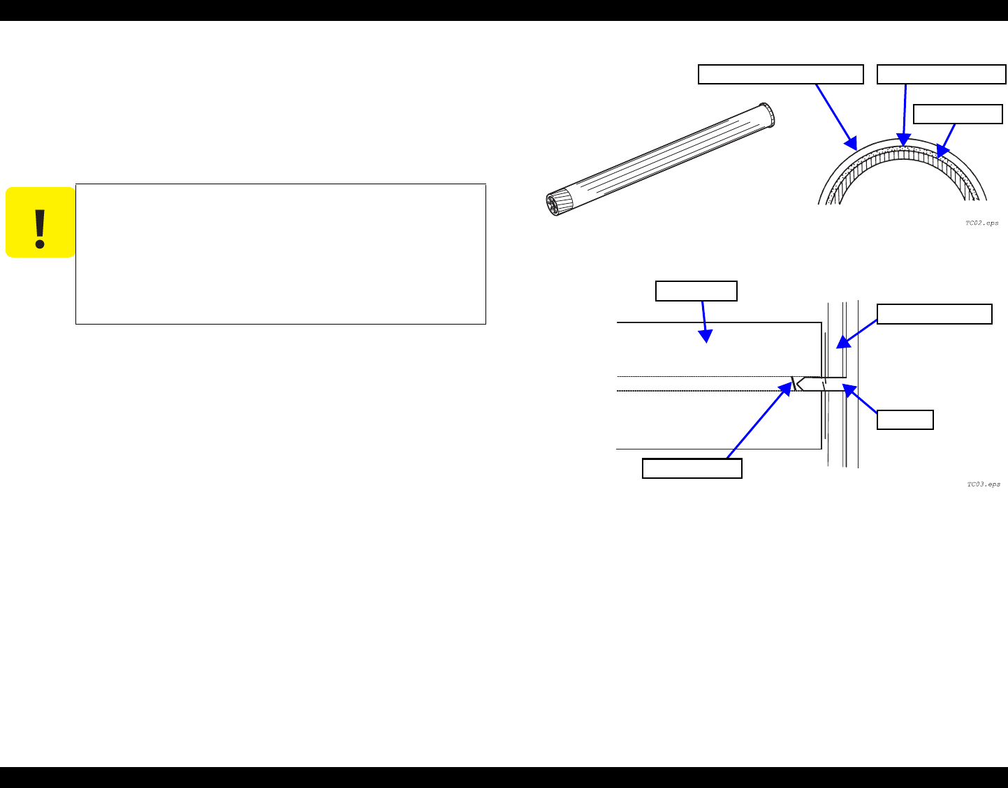
Grounding of OPC drum:
The grounding contact of the photoconductor is located in its front inside and
always in contact with the shaft of the front plate of the print unit. When the print
unit is installed in the printer body, the setting pin of the print unit front plate
comes in contact with the front plate of the printer body to achieve grounding.
Thus, the electric charge on the photoconductor in the area exposed to light is
grounded through the grounding plate, the shaft and the setting pin to the frame.
(See
“Figure 2-15”)
Figure 2-14. OPC Drum
Figure 2-15. Grounding of OPC drum
C A U T I O N
Precautions in Handling:
The organic photoconductor can deteriorate by sensitivity change
due to light fatigue if it is exposed to light for an extended period of
time. To prevent such deterioration, when the OPC Drum has been
taken out of the printer body, cover it with a clean soft cloth to
protect it from exposure to light. In handling the Photoconductor
Unit, take great care that no dirt adheres to the surface of the
photoconductor.
Electric charge retaining layer Carrier generation layer
Aluminum base
OPC Drum
Grounding Plate
Front Plate Assy
Shaft