
Specifications


EPSON EPL-N1600 Chapter 4 Disassembly and Assembly
Rev. A 4-121
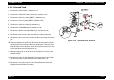
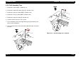
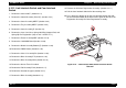
4.3.12 Actuator Registration
1. Remove the Cover Side,E. (Section 4.2.1)
2. Remove the Control Assembly Panel (E). (Section 4.2.3)
3. Remove the Cover Assembly MBF.E.(Section 4.2.4)
4. Remove the Tray Assembly MBF.E.(Section 4.2.5)
5. Remove the Cover Assembly,E. (Section 4.3)
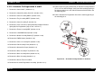
6. Remove the Lever Jam Clear, Sprin
g
-Hold Rod, Stopper Rod, and
Sprin
g
Nip Pre-Re
g
istration (steps 6 and 7 of RRP 4.1.1).
7. Remove the Frame Assembly MBF.(Section 4.3.19)
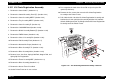
8. Remove C258MAIN Board.(Section 4.3.49)
9. Remove Shield Assembly Bottom (E).(Section 4.3.44)
10. Remove PWBA Hotaru.(Section 4.3.48)
11. Remove the Chassis Assembly PS.(Section 4.3.46)
12. Remove the Roll Assembly Feed.(Section 4.3.7)
13. Remove the Actuator No Paper.(Section 4.3.8)
14. Remove the Drive Assembly-F/P.(Section 4.3.42)
15. Remove the Drive Assembly Main.(Section 4.3.43)
16. Remove the Drive Assembly.(Section 4.3.3)
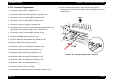
17. Remove the Sensor Tone if installed.
18. Remove the Kit Chute Re
g
istration Assembly. (Section 4.3.11)
19. Pull the Actuator Re
g
istration, alon
g
with the Sprin
g
Sensor
Re
g
istration, out of the retainin
g
holes in the mountin
g
posts on the
Printer Frame.
Figure 4-18. “Actuator Registration” Removal