
Specifications


EPSON EPL-N1600 Chapter 4 Disassembly and Assembly
Rev. A 4-139
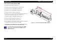
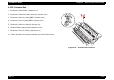
4.3.30 Sensor Assembly Photo Exit
1. Remove the Cover Side,E. (Section 4.2.1)
2. Remove the Control Assembly Panel (E). (Section 4.2.3)
3. Remove the Cover Assembly MBF.E.(Section 4.2.4)
4. Remove the Tray Assembly MBF.E.(Section 4.2.5)
5. Remove the Cover Assembly,E. (Section 4.3)
6. Remove the C258MAIN Board.(Section 4.3.49)
7. Remove Shield Assembly Bottom (E).(Section 4.3.44)
8. Remove PWBA Hotaru.(Section 4.3.48)
9. Remove the Chassis Assembly PS. (Section 4.3.46)
10. Set the printer on the front surface.
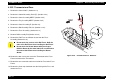
11. Press and release the latches of the Sensor Assembly Photo Exit
and remove the Sensor from the Printer Frame (1).
12. Disconnect J281 from the Sensor.
Figure 4-36. “Sensor Assembly Photo Exit” Removal